Centrifugal method and apparatus for devolatilizing polymers

A technology for devolatilization and polymers, which is applied to remove volatile substances in thermoplastic polymers. From the thermoplastic field, it can solve the problems of unable to produce spherical devolatilization polymers, etc.

Inactive Publication Date: 2001-07-25
DOW GLOBAL TECH LLC
View PDF5 Cites 3 Cited by
  • Summary
  • Abstract
  • Description
  • Claims
  • Application Information

AI Technical Summary

Problems solved by technology

Additionally, Haw's method and apparatus do not produce spherical devolatilized polymers

Method used


Image

  • Centrifugal method and apparatus for devolatilizing polymers
  • Centrifugal method and apparatus for devolatilizing polymers
  • Centrifugal method and apparatus for devolatilizing polymers

Examples


Embodiment Construction

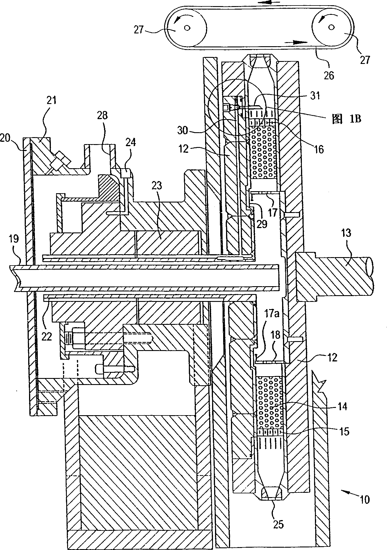
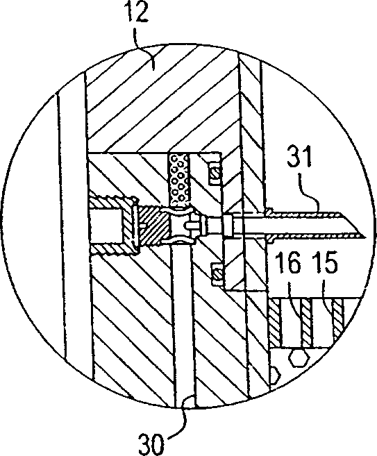
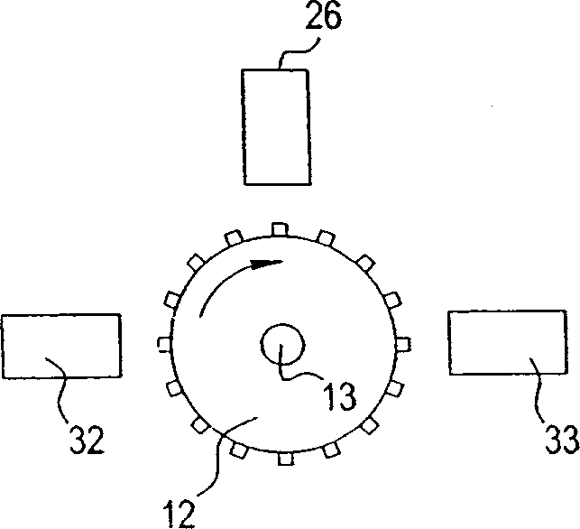
[0008] Referring now to FIG. 1, there is shown a side cross-sectional view of an embodiment of an apparatus 10 of the present invention. The device 10 comprises a disc-shaped chamber 12 which rotates by means of a shaft 13 about the longitudinal axis of said shaft 13 . The shaft 13 is driven to rotate by a motor (not shown). The chamber 12 comprises an annular ring of nickel-chromium metal open cell foam packing 14 cut from a large workpiece of material, preferably by an electrode discharge machining process. The filler 14 is Celmet Brand #1 material available from Sumitomo Electric USA, NY, NY. An annular support belt 15 surrounds said packing 14 . The support strip 15 is perforated with holes 16 . An annular distribution belt 17 is placed inside said packing 14 . The dispensing strip 17 is perforated with holes 18 .

[0009] A polymer conduit 19 extends into chamber 12 and terminates in the chamber. The polymer conduit 19 includes a flange 20 and a sealing mounting bod...


PUM

PropertyMeasurementUnit
pressureaaaaaaaaaa

Abstract

A method for devolatilization of a thermoplastic polymer containing at least one volatile component which includes the following three steps: heating the termoplastic polymer so that the thermoplastic polymer is a heated liquid or molten thermoplastic polymer, flowing the heated liquid thermoplastic polymer through a packed bed liquid-gas contactor by centrifugal force, and flowing a stripping gas through the packed bed countercurrent to the flow of the heated liquid thermoplastic polymer so that the volatile component volatilizes into the stripping gas from the heated liquid thermoplastic polymer by gas-liquid contacting in the packed bed; and an apparatus therefor.

Description

Background technique [0001] The present invention relates to the removal of volatile species from thermoplastic polymers, and more particularly to methods and apparatus for the removal of volatile species from thermoplastic polymers using centrifugal force. [0002] U.S. Patent 3,409,712 to Chisholm, fully incorporated herein by reference, discloses a method for removing volatiles from thermoplastic polymers by melting the polymer and flowing the molten polymer over the surface of a rotating disk. methods and equipment. US Patent No. 3,424,832 to Chisholm, which is fully incorporated by reference, discloses a method and apparatus for pelletizing thermoplastic polymers using a rotating chamber or hollow rotor. U.S. Patent 4,940,472 to Hay II et al., fully incorporated by reference, discloses a method for removing volatile compounds from thermoplastic polymers by melting the polymer and flowing the molten polymer over the surface of a rotating disk. Substance methods and appar...

Claims


Application Information

Patent Timeline
Patent Type & Authority Applications(China)
IPC IPC(8): B01D19/00B01J10/00B01J19/18B01J19/28C08F6/00C08F6/28
CPCC08F6/28B01D19/0052B01J2219/00121B01J10/005B01J19/18B01J19/0066B01J10/002B01J2219/00159B01J19/0073B01J19/28C08F6/005B01D19/0005Y02P20/141
Inventor 丹·特托威德约约小乔治·J·夸德德克拉克·J·克明斯尤金·R·摩尔
Owner DOW GLOBAL TECH LLC
Why Eureka
Try Eureka