Piston engine

A piston-type, mechanical technology, applied in the direction of pistons, reciprocating piston engines, mechanical equipment, etc., can solve the problems of inability to prevent wear and reduce inertial force, and achieve the effects of wear and efficiency improvement, large inertial force and small friction

Inactive Publication Date: 2007-02-07
格哈特·莱霍弗
View PDF6 Cites 0 Cited by
  • Summary
  • Abstract
  • Description
  • Claims
  • Application Information

AI Technical Summary

Problems solved by technology

Due to the use of wave-shaped rollers, this greatly reduces the inertial force, and thus avoids possible rotation when using rollers, but the rollers still move axially during the rising phase of the cam disc, so relatively large rollers cannot be prevented. wear and tear
In addition, in this embodiment there is also a reaction force acting on the cylinder wall through the piston, so this also produces a large wear

Method used


Image

  • Piston engine
  • Piston engine
  • Piston engine

Examples


Embodiment Construction

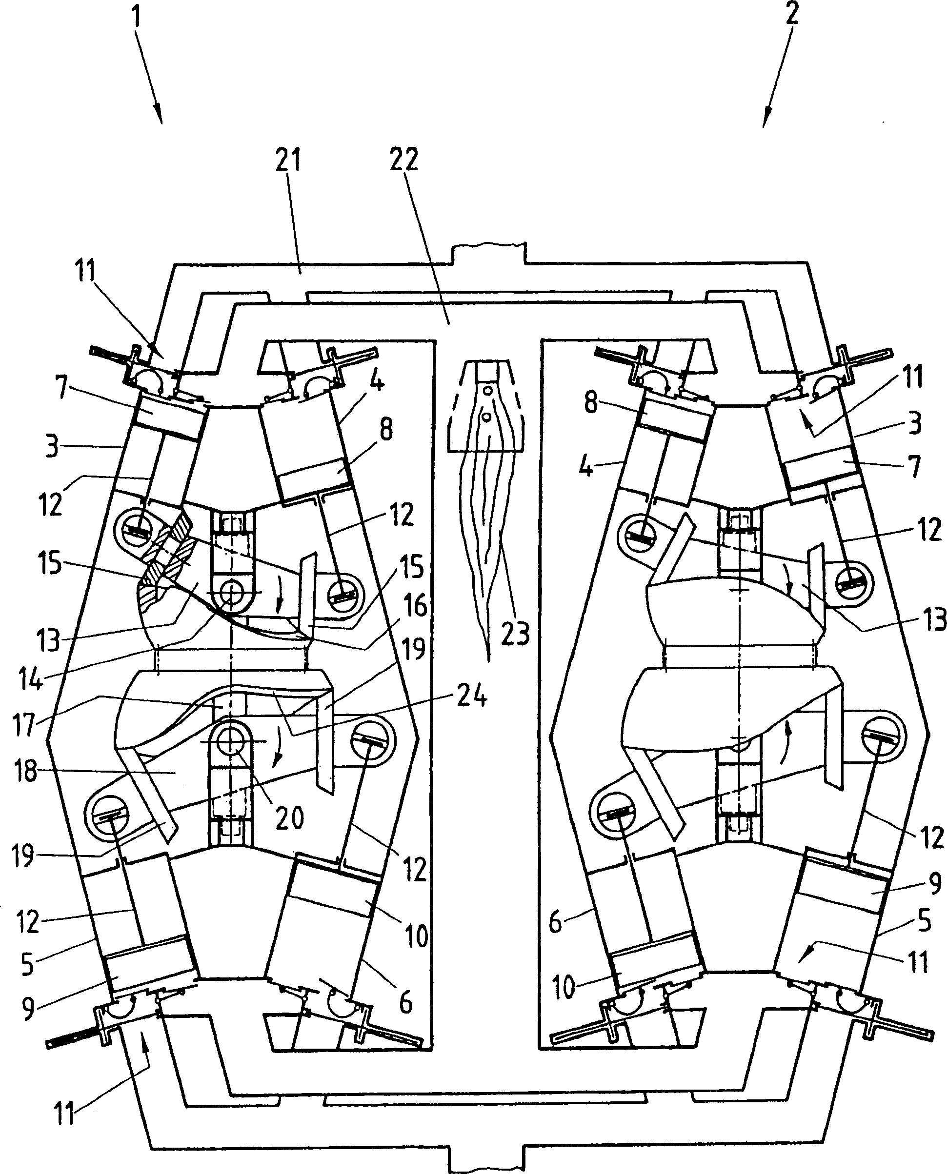
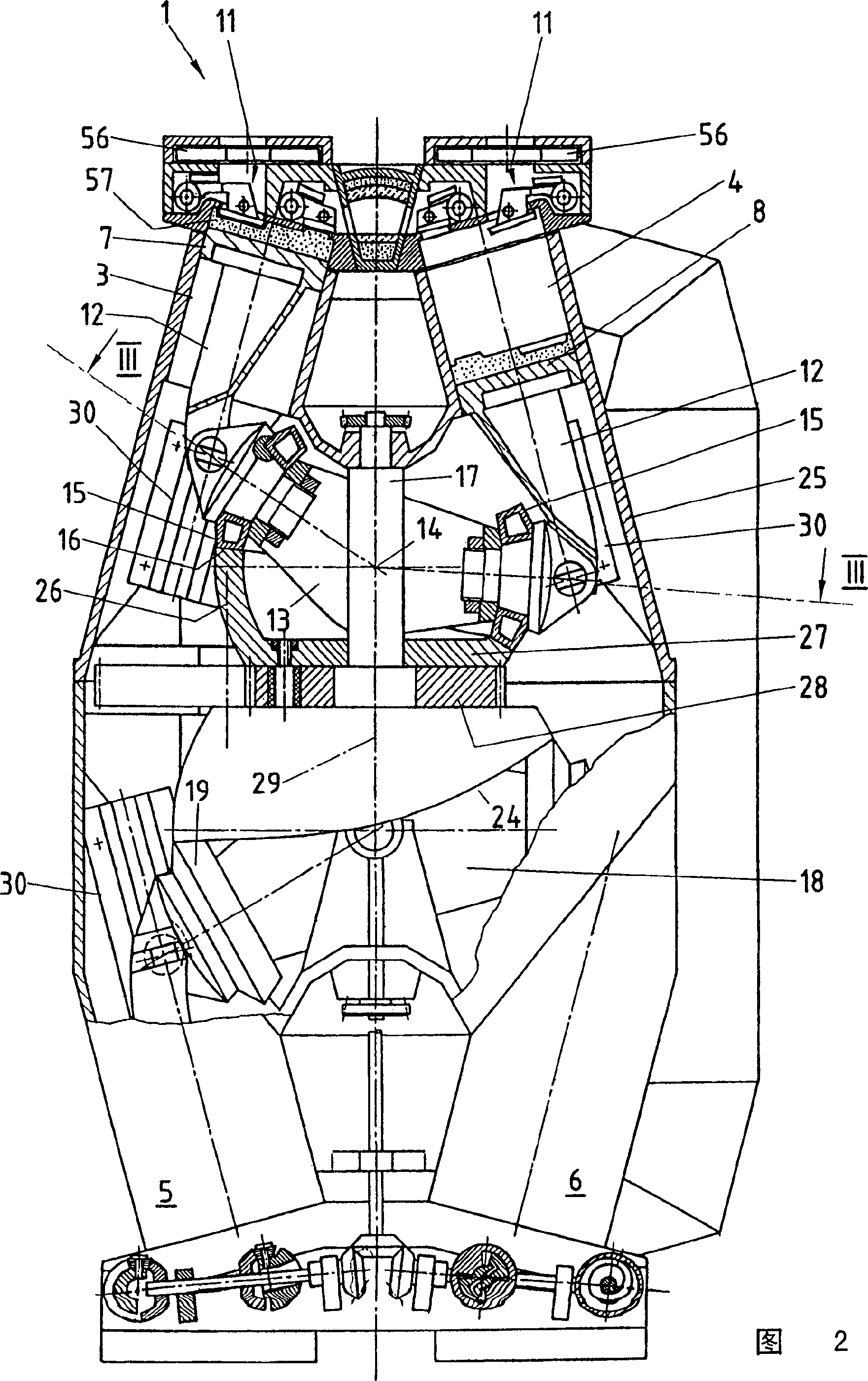
[0031] Such as figure 1 As shown, the piston machine designed as a heat engine comprises two banks 1 and 2 with four cylinders 3, 4, 5 and 6 each. Arranged in each cylinder 3, 4, 5 and 6 is a piston 7, 8, 9 or 10, which can move linearly. Each cylinder 3 to 6 is provided with a valve device 11, with this device just can open and close the air inlet or exhaust hole of each gas 3 to 6, and these valve devices 11 also hereinafter described in detail.

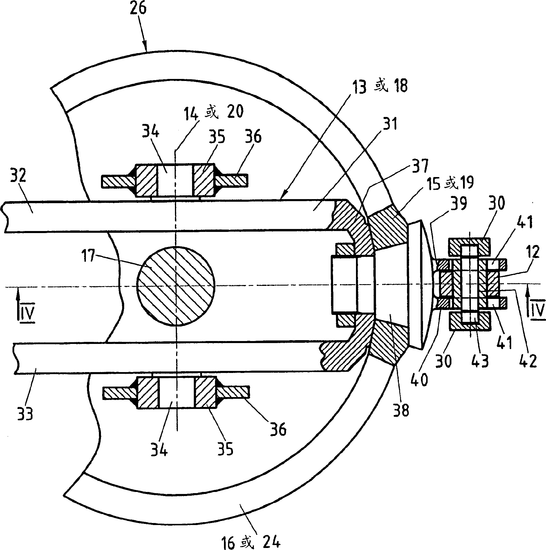
[0032] A connecting rod 12 is fixedly connected to each of the pistons 7, 8, 9 and 10. The connecting rod 12 connected with the piston 7 moving in the cylinder 3 is hinged on one end of the rocker 13 . The connecting rod 12 of the movable piston 8 in the cylinder 4 is articulated on the other end of the rocker 13 . The rocker 13 can pivot centrally around a pivot axis 14 which is fixed on the housing of the piston mechanism, as will be described in more detail below.

[0033] Similarly, a roller 15 is respectively arranged at b...


PUM


Abstract

The invention relates to a piston engine comprising a case (25) containing at least two cylinders (3, 4; 5, 6) with inlet openings and outlet openings, which can be opened and closed by means of controllable valves. Each piston (7, 8, 9, 10) can linearly move inside said cylinders (3, 4, 5, 6) in a reciprocating manner. The inventive piston engine also comprises at least one shaft (17), which is rotatably mounted in the case (25), and a transmission device, with which the linear reciprocating motion of the pistons (7, 8, 9, 10) can be converted into a rotational movement of the shaft (17) or the rotational movement of the shaft (17) can be converted into a linear reciprocating motion of the pistons (7, 8, 9, 10). The transmission device comprises a pivotal lever (13; 18) which can be pivoted around a centrally arranged pivot pin (14; 20) mounted in the case (25). A rotatable roller (15; 19) is placed on each of said pivotal levers (13; 18) at both end areas thereof. The rotational axes of the rollers are each perpendicular to the pivot pin (14; 20), and the rollers (15; 19) roll on a track (16) which is joined to the shaft (17) in a fixed manner while extending between both rollers (15; 19), and which is provided with elevations and recesses. Said elevations and recesses are matched to one another such that the rollers (15; 19) located opposite one another on the pivotal lever (13; 18) are in contact with the track, and such that a connecting rod (12), which is connected to the appropriate piston (7, 8, 9, 10), is additionally joined to both end areas of the pivotal lever (13; 18).

Description

technical field [0001] The present invention relates to a piston machine. Background technique [0002] Piston machines of this type are well known. In particular, piston engines based on the Otto cycle or the Diesel cycle are known, in which the linear reciprocating motion of the piston is converted into a rotary motion via a connecting rod interacting with a crankshaft. The movement of the piston is thus sinusoidal, the course of the movement of the piston cannot be influenced, so that, for example, an optimization of the combustion process is not possible for low-pollutant combustion internal combustion engines. [0003] In EP-A-0702128 a mechanism is shown with which the reciprocating motion of the piston can be converted into a rotational motion of a shaft via a cam disc. Due to the use of the cam discs, the motion characteristics of the piston can be adapted and optimized to the desired process, but with the arrangement shown here alternating forces, especially trans...

Claims


Application Information

Patent Timeline
Patent Type & Authority Patents(China)
IPC IPC(8): F02B75/26F01B3/04F01B3/00F01L7/06F01L33/04F02B67/00F16H21/44F16J1/12F16J15/16
CPCF01B3/0005F01B3/045F02B75/26
Inventor 格哈特·莱霍弗
Owner 格哈特·莱霍弗
Why Eureka
Try Eureka