
Electric dust collector

A vacuum cleaner, electric technology, applied in the direction of vacuum cleaners, suction filters, cleaning filter devices, etc., can solve the problem of long distance

Inactive Publication Date: 2007-01-24
SANYO ELECTRIC CO LTD
View PDF6 Cites 0 Cited by
  • Summary
  • Abstract
  • Description
  • Claims
  • Application Information

AI Technical Summary

Problems solved by technology

[0008] However, even if this method is applied to the above-mentioned commercially available exhaust return type electric vacuum cleaner, since the distance between the ozone generator and the filter arranged on the downstream side of the blower motor is very long, the filter cannot be cleaned. Sterilization

Method used


Image

  • Electric dust collector
  • Electric dust collector
  • Electric dust collector

Examples


Embodiment Construction

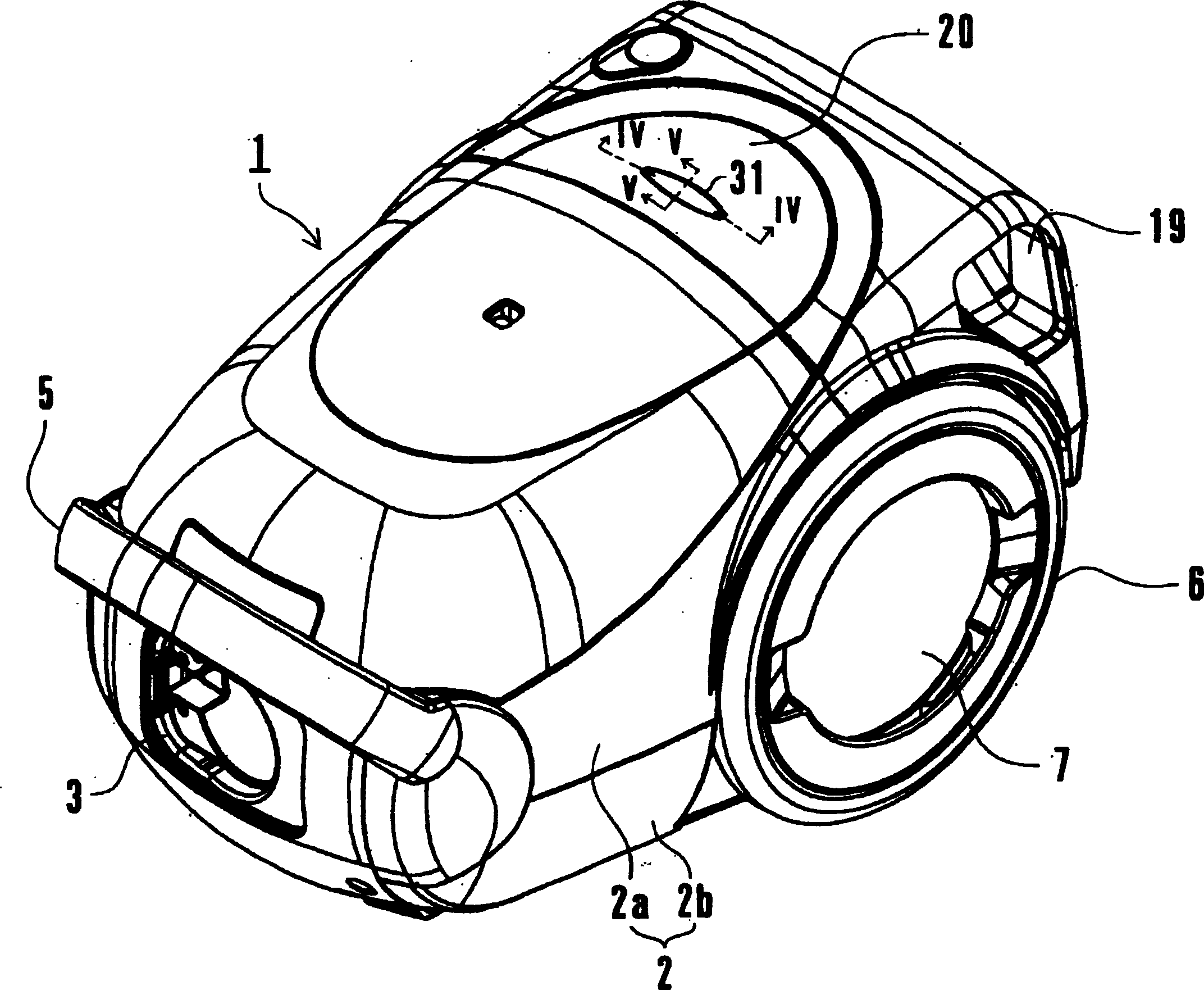
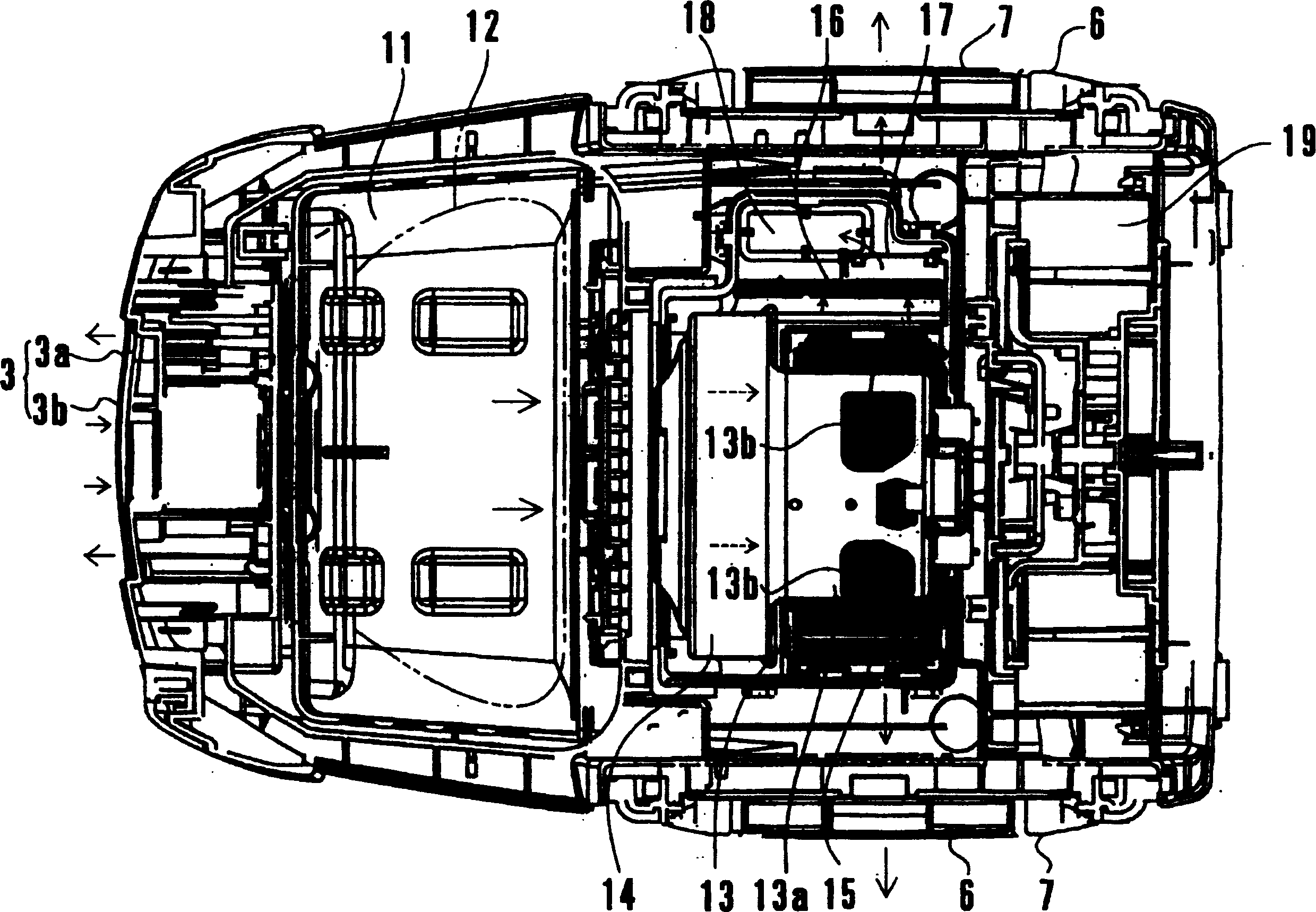
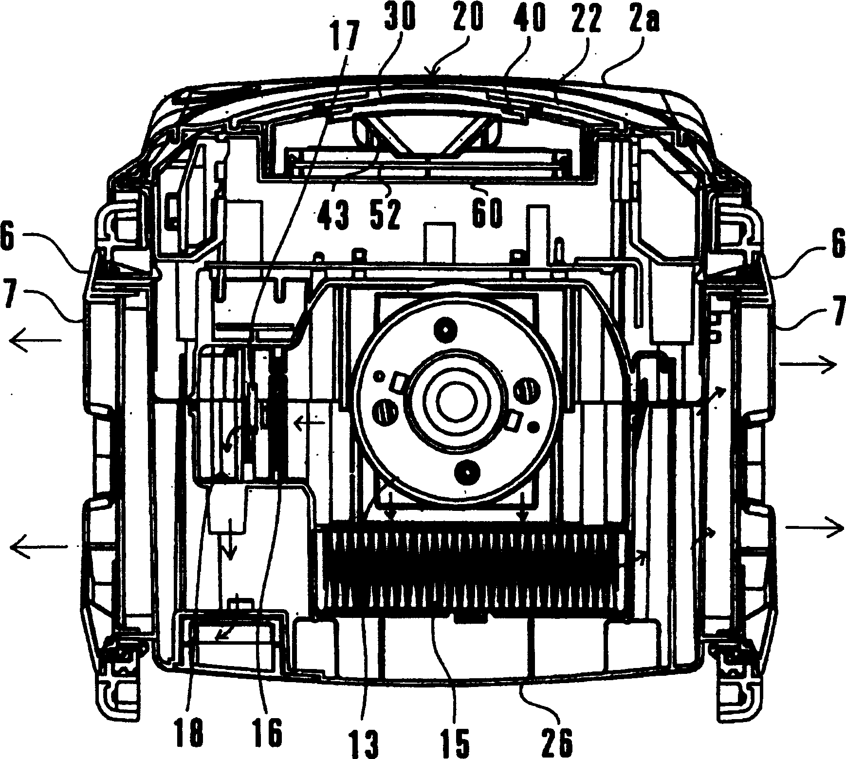
[0022] Below, according to Figure 1 to Figure 6 Examples of the present invention will be described. figure 1 It is an external perspective view of the vacuum cleaner body of the electric vacuum cleaner according to the embodiment of the present invention. figure 2 It is a top view of the state where the upper case of the vacuum cleaner main body was removed. image 3 It is a front sectional view of the vacuum cleaner body. Figure 4 yes figure 1 Sectional view of line IV-IV in the middle. Figure 5 In the state where no external force acts on the display lens, figure 1 The cross-sectional view of the V-V line in the middle. Figure 6 In a state where an external force acts on the display lens, figure 1 The cross-sectional view of the V-V line in the middle. and, figure 2 and image 3 In , solid or dashed arrows indicate the air flow direction.

[0023] The electric vacuum cleaner of embodiment, in figure 1 The hose connection port 3 of the shown vacuum cleaner b...


PUM


Abstract

The vacuum cleaner includes a hose connection port provided at the front end of a vacuum cleaner body and connecting a connection hose, an exhaust port provided at the vacuum cleaner body, the blower commutator motor provided in the vacuum cleaner body, a filter provided in an air passage between the commutator motor and the exhaust port and an ozone generator provided in an air passage from the filter to the exhaust port and adjacent to the filter. The ozone generator is controlled to be operated in a predetermined time period after a blower is stopped. To provide a vacuum cleaner allowing sterilization of a filter disposed on the downstream side of a blower commutator motor.

Description

technical field [0001] The present invention relates to an electric vacuum cleaner, in particular to the sterilization of a filter provided between a commutator motor for a blower and an exhaust port of a vacuum cleaner body. Background technique [0002] In conventional electric vacuum cleaners, the dust-containing air sucked in from the suction port enters the dust collection chamber and is removed by the dust collection bag, and then is distributed to the exhaust port for releasing the air to the outside of the machine through the blower, the motor for the blower, and The air is sent to the return exhaust port of the return flow path for exhaust (refer to JP-A-2001-178664). In addition, in this electric vacuum cleaner, a commutator motor is used as the motor for the blower similarly to the conventional general structure. In this commutator motor, carbon powder is generated and scattered by the contact between the carbon brushes of the motor and the commutator due to the ...

Claims


Application Information

Patent Timeline
Patent Type & Authority Patents(China)
IPC IPC(8): A47L7/04C01B13/10A47L5/14A47L7/00
CPCA47L7/04A47L9/12A47L9/20A61L2/202
Inventor 松桥弘道森田明宏藤吉俊行松本千寿代山崎昭雄
Owner SANYO ELECTRIC CO LTD
Learn More