
Tubing pump deivce

A technology of tube pumps and limit devices, which is applied in pumps, liquid variable displacement machines, pumps with flexible working elements, etc., can solve problems such as cracks and cracks, and achieve the effect of long life

Inactive Publication Date: 2007-01-17
SANKYO SEIKI MFG CO LTD
View PDF5 Cites 0 Cited by
  • Summary
  • Abstract
  • Description
  • Claims
  • Application Information

AI Technical Summary

Problems solved by technology

[0006] When the edges of the rollers flatten the elastic tube, there is a problem of stress concentration on the bent portion of the elastic tube and cracks or cracks due to repeated fatigue

Method used


Image

  • Tubing pump deivce
  • Tubing pump deivce
  • Tubing pump deivce

Examples

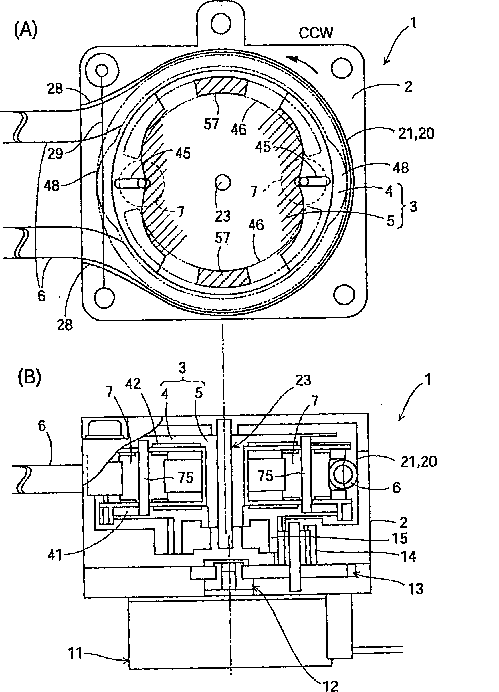
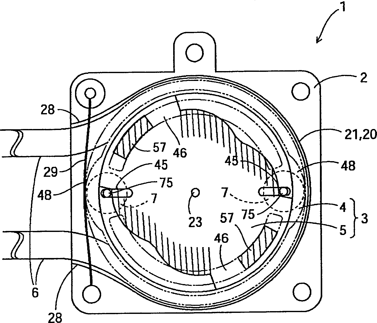
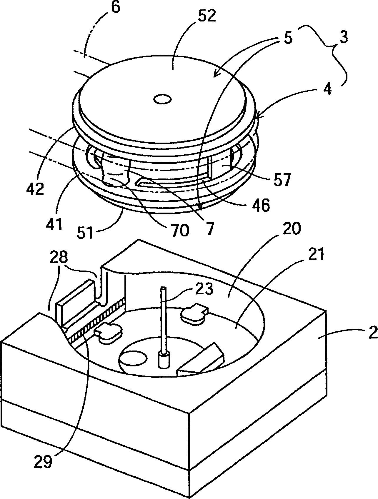

Embodiment Construction

[0026] Embodiments of the present invention will be described with reference to the drawings.

[0027] figure 1 (A) and (B) are explanatory plan views showing main parts of a tube pump device in an applied form and a cross-sectional view of the pump device. figure 2 From figure 1 An explanatory diagram of the timing at which liquid delivery starts in the state shown in (A). image 3 It is a perspective view which shows the state which disassembled the tube type pump apparatus of this form into a casing and a rotating body. Figure 4 (A) and (B) represent the image 3 The shown rotating body is disassembled into a perspective view of a roller support body, a pair of end plates, and rollers for crushing a pipe, and a perspective view of a pair of support plates viewed from obliquely below the lower support plate. Figure 5 (A), (B), and (C) are a plan view, an A-A' sectional view, and a bottom view of the roller support, respectively. Image 6 (A) and (B) are the front vie...


PUM


Abstract

A tube type pumping apparatus having a resilient tube provided along a wall, a squeezing member positioned to move along the wall to squeeze the resilient tube against the wall, a squeezing member holder that holds the squeezing member; a cam member whose surface receives a driving force from a driving source to change positions of the squeezing member between an initial position away from the wall and a squeezing position near the wall, and a regulating force generator that provides a regulating force to the squeezing member at a transition time interval as the squeezing member moves from the initial position to the squeezing position. The regulating force generator and the cam member acting together to prevent the squeezing member from applying pressure against the resilient tube during the transition time interval. The squeezing member has a curved surface to maintain an alignment of the tube with the squeezing member.

Description

technical field [0001] The present invention relates to a tube-type pump device in which a crushing member moves while crushing an elastic tube to transport liquid in the tube. Background technique [0002] When the elastic tube is crushed by a crushing member such as rolling the tube, the tube pump device that moves the crushing member along the elastic tube to transport the liquid in the tube may be used in food, cosmetics, pharmaceuticals, chemicals, etc. used in the field. [0003] In such a pump device, a cam body that transmits the driving force from a driving source and a roller support body that supports a roller for crushing a pipe are generally provided, and the cam surface formed on the cam body is used to move the roller from the The elastic tube is crushed with a roller from the withdrawn position to the crushed position. [0004] However, in the case of a cam mechanism, when the roller is displaced by the cam surface, the cam does not work because the roller ...

Claims


Application Information

Patent Timeline
Patent Type & Authority Patents(China)
IPC IPC(8): F04B43/08F04B43/12
CPCF04B43/1253
Inventor 伊藤秀明
Owner SANKYO SEIKI MFG CO LTD
Learn More