Assembly and method for cutting strands formed by thermoplastics filaments

A technology of plastic material and string, which can be used in the direction of forming non-bundle, manufacturing tools, glass manufacturing equipment, etc., can solve the problems of complex system and so on

Inactive Publication Date: 2007-01-10
SAINT GOBAIN VETROTEX FRANCE
View PDF11 Cites 0 Cited by
  • Summary
  • Abstract
  • Description
  • Claims
  • Application Information

AI Technical Summary

Problems solved by technology

[0021] However, the system is more complex

Method used


Image

  • Assembly and method for cutting strands formed by thermoplastics filaments
  • Assembly and method for cutting strands formed by thermoplastics filaments
  • Assembly and method for cutting strands formed by thermoplastics filaments

Examples


Embodiment Construction

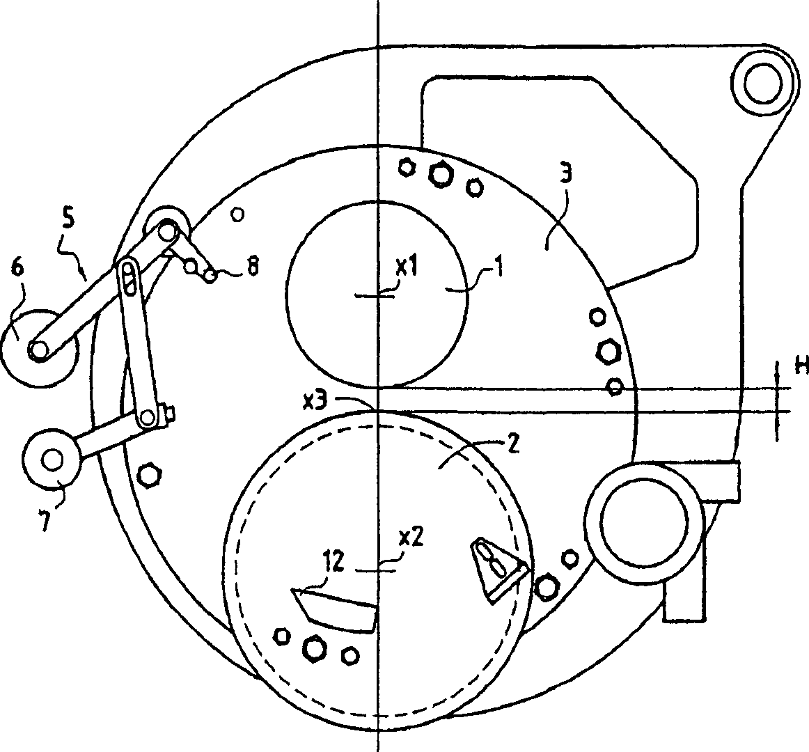
[0054] figure 1 The main elements of the invention are shown in .

[0055] As is known, this cutting machine comprises a knife wheel 1 equipped with knives protruding along its radius. The cutting tool is not shown in the figure. The cutting machine also comprises an anvil wheel 2, the axis x2 of which is parallel to the axis x1 of the knife holder wheel 1; when the two wheels approach each other, they come into contact by their generatrices and rotate in opposite directions to each other, thus producing cutting area.

[0056] The respective tangential speeds of the wheels 1, 2 must of course be equal and the clamping between the wheels 1, 2 can be adjusted according to the different parameters of the cutting such as the diameter of the fibers that make up the string, the properties of the string, the cutting speed ... moment.

[0057] In addition, a processing wheel 4 can be arranged close to the anvil wheel 2 in order to dress the outer surface of the anvil wheel 2 when ...


PUM


Abstract

An assembly and associated method for cutting strands formed by thermoplastic filaments. The assembly includes a blade-holder wheel and an anvil-wheel rotating in reverse directions about two parallel axes, and at least a mechanism for actuating the wheels and for contacting a strand with the anvil wheel. The assembly further includes a mechanism oscillating the support of the wheels, whereof the axis of the support is parallel to the axis of the wheels, and an associated actuator. A mechanism for contacting the wheels is designed in particular to pinch the strand and the associated actuator for passing the strand between the blade-holder wheel and the anvil-wheel when the wheels are not in contact.

Description

technical field [0001] The present invention relates to the production of strings composed of cut thermoplastic material fibers, in particular glass fibers, and more particularly to a cutting method and assembly for one such production. Background technique [0002] The cutting of a string (sometimes called a thread) is obtained in a known manner by passing the fibrous material between a wheel called an anvil and a cutting wheel equipped with knives protruding uniformly around its Rotate in the opposite direction. An anvil wheel, usually composed of an elastomer of the polyurethane type, is arranged in contact under pressure with the edge of a knife protruding from the cutting wheel, thereby defining a cutting zone. [0003] In order to keep such a device at the preferred yield level, the cutting must of course be carried out in a continuous manner with the least possible downtime. Downtime is basically caused by a break in the supplied line. The cutting device should be ...

Claims


Application Information

Patent Timeline
Patent Type & Authority Patents(China)
IPC IPC(8): D01G1/04C03B37/16B26D1/40
CPCC03B37/16Y10S83/913D01G1/04Y10T83/768Y10T83/0605Y10T83/051Y10T83/8804Y10T83/7788
Inventor D·丰特H·普雷沃斯托L·贝特伦
Owner SAINT GOBAIN VETROTEX FRANCE
Why Eureka
Try Eureka