Motor driving device
A motor drive and control device technology, applied in the direction of starting devices, measuring devices, motor control, etc., can solve problems such as complex calculations, easy loss of synchronization, and out of step
- Summary
- Abstract
- Description
- Claims
- Application Information
AI Technical Summary
Problems solved by technology
Method used
Image

Examples
Embodiment 1
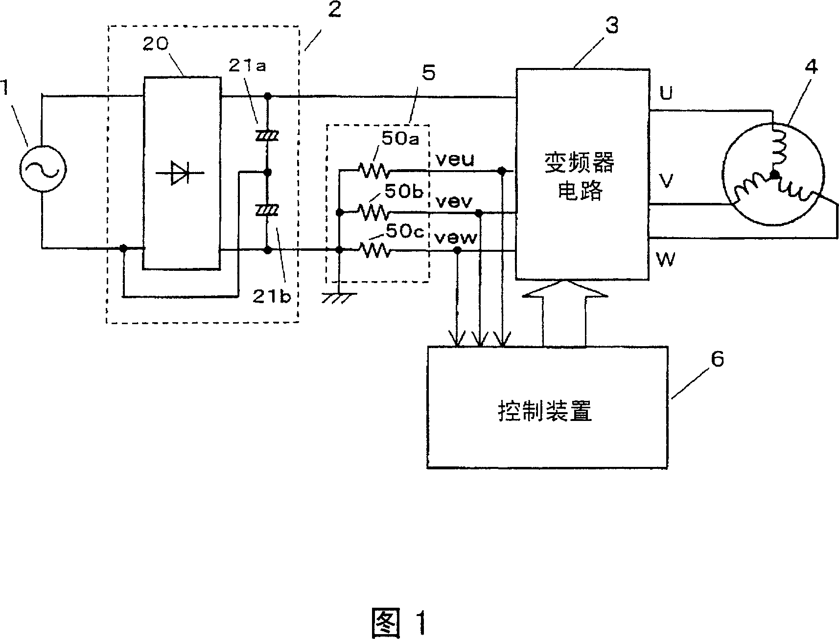
[0035] Fig. 1 is a block diagram of a motor drive device in the first embodiment. In FIG. 1 , AC power supply 1 adds AC power to rectifier circuit 2 and converts it into DC power. Such DC power is then converted into 3-phase AC power by inverter circuit 3 to drive motor 4 . Capacitors 21a, 21b are connected in series between the DC output terminals of the full-wave rectifying circuit 20 in the rectifying circuit 2, and the connection point between the capacitors 21a, 21b is connected with an input terminal of the AC power supply to form a DC voltage doubler circuit to improve The voltage applied to the inverter circuit 3.
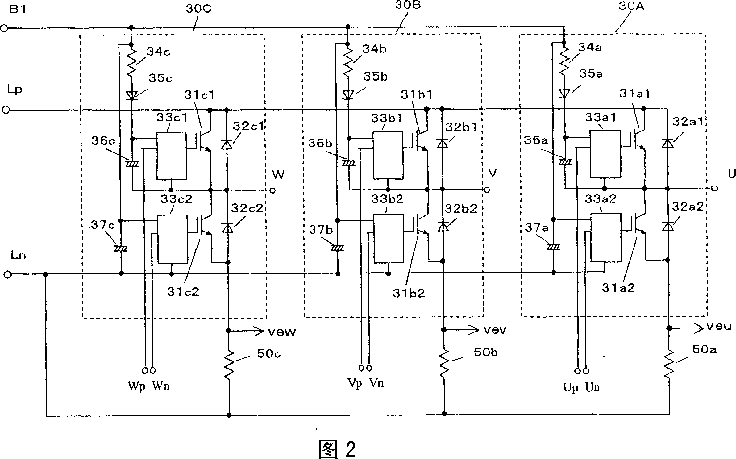
[0036] The negative voltage side of the inverter circuit 3 is connected with a current detection device 5. By detecting the current flowing in the lower arms of the three phases of the inverter circuit 3, the output current of the inverter circuit 3, that is, the current of each phase of the motor 4 to test.
[0037] The control device 6 calculates the ou...
Embodiment 2
[0089] The second aspect of the present invention will be described below using Fig. 12, Fig. 13, Fig. 14 and Fig. 15.
[0090] Example.
[0091] Fig. 12 is a cross-sectional view of the motor drive device of the dishwasher in the second embodiment of the present invention, where the water pump and the motor adopt a single-motor-single-water-pump mode.
[0092] Wherein, tap water is added in the cleaning tank 7 from the water inlet valve 8, and the cleaning water 9 is accumulated in the cleaning tank 7. The bottom of the cleaning tank 7 is provided with a flat DC brushless motor 4a, the rotation axis of which is in the vertical direction, and the bottom of the motor 4a is provided with a water pump housing 10 . By rotating the impeller 11, a pressure is applied to the water in a centrifugal direction from the axis of rotation.
[0093] When the impeller 11 rotates in the forward direction, the washing water is sprayed from the spraying wings 12b provided with the spraying no...
Embodiment 3
[0110] Fig. 17 is a block diagram of the control device of the motor drive device in the third embodiment. The control device controls the reactive current Isinφ after detecting the motor torque, so as to maximize the working efficiency.
[0111] FIG. 17 is a partial improvement of the block diagram shown in FIG. 13 in the second embodiment, so only the improved part will be described below. Wherein, the output electric power calculation device 77 of the frequency converter calculates the output electric power of the frequency converter, that is, the input power of the motor from the output voltage Va of the frequency converter and the effective current Ia, and the input signal of the motor and the driving frequency signal are added to the torque current calculation device 79 On, and then according to the formula 6 to find the motor torque current Iq.
[0112] Active current calculation device 80 obtains motor current vector absolute value Im from formula 2, and motor current ...
PUM
 Abstract
Description
Claims
Application Information
 - Generate Ideas
- Intellectual Property
- Life Sciences
- Materials
- Tech Scout
- Unparalleled Data Quality
- Higher Quality Content
- 60% Fewer Hallucinations
Browse by: Latest US Patents, China's latest patents, Technical Efficacy Thesaurus, Application Domain, Technology Topic, Popular Technical Reports.
© 2025 PatSnap. All rights reserved.Legal|Privacy policy|Modern Slavery Act Transparency Statement|Sitemap|About US| Contact US: help@patsnap.com