
Optical membrane and LCD using same

A technology of optical film and liquid crystal layer, which is applied in the field of optical film and can solve problems such as size change

Inactive Publication Date: 2007-01-03
NITTO DENKO CORP
View PDF15 Cites 0 Cited by
  • Summary
  • Abstract
  • Description
  • Claims
  • Application Information

AI Technical Summary

Problems solved by technology

In addition, not only the size change of the polarizer can cause this problem, but the brightness enhancement film itself can also be affected by heat or high temperature and humidity conditions

Method used

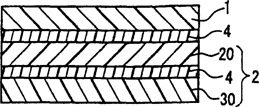
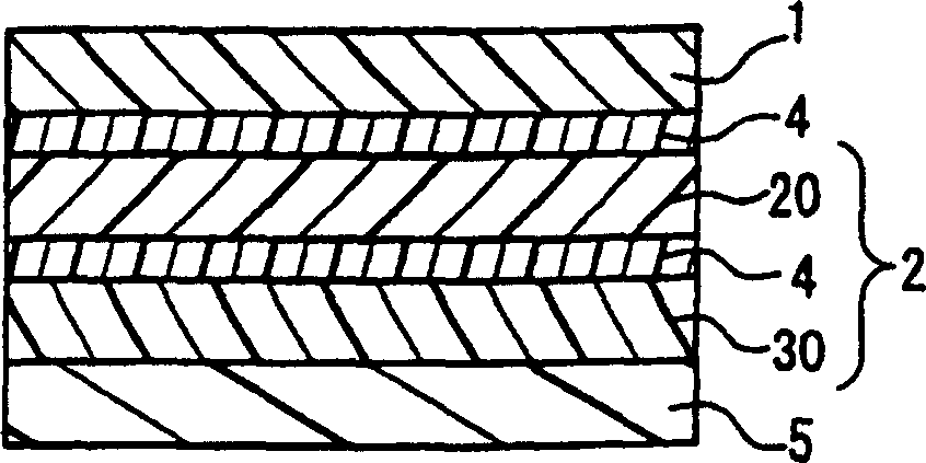
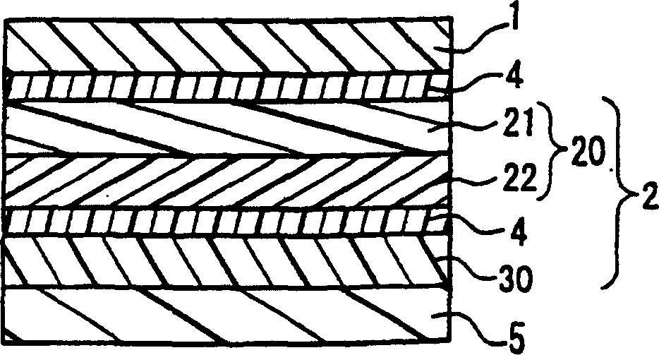

Image

  • Optical membrane and LCD using same
  • Optical membrane and LCD using same
  • Optical membrane and LCD using same

Examples


Embodiment

[0114] The present invention will be further described below by way of examples and comparative examples, and the following examples will not limit the scope of the present invention.

[0115] Embodiment A and comparative example A

Embodiment A-1

[0117] First, a PVA film containing iodine and having a thickness of 30 μm was made into a polarizing plate. A TAC film with a thickness of 40 μm was bonded on both surfaces of the polarizing plate as a transparent protective film with a PVA-based adhesive, and the total thickness of the obtained polarizing plate was 110 μm.

[0118] Thereafter, a brightness enhancement film comprising a circularly polarized light separation layer and a λ / 4 plate was manufactured as follows. First, a cholesteric liquid crystal polymer (prepared according to the method of JP8(1996)-239496A) represented by the following molecular formula (1) was mixed with cyclohexanone to prepare a liquid crystal polymer solution with a concentration of 30% by weight. In formula (1), n:m=80:20, and the molecular weight is about 10000. The polymer solution was coated on an oriented substrate (TAC film) with a thickness of 40 μm, and dried at 160° C. for 2 minutes to form a circularly polarized light separation ...

Embodiment A-2

[0126] A cellulose diacetate film (manufactured by Nitto Denko Corporation) having a thickness of 100 μm and Δnd(450 nm) / Δnd(550 nm)=0.96 was uniaxially stretched to 1.4 times the original length as a λ / 4 plate having a thickness of 80 μm. An optical film with a thickness of 300 μm was produced in a similar manner to Example A-1 except that the λ / 4 plate was changed. The Δnd(450nm) / Δnd(550nm) of gained λ / 4 film and λ / 4 plate are all 0.96, and the photoelastic coefficient of λ / 4 film is 18.4×10 -12 m 2 / N.


PUM

PropertyMeasurementUnit
photoelasticityaaaaaaaaaa
lengthaaaaaaaaaa
photoelasticityaaaaaaaaaa

Abstract

An optical film in which a function of a brightness enhancement film is maintained and variations in brightness and chromaticity within a film plane are suppressed is provided. An optical film is a laminate of an absorptive dichroic polarizing plate and a brightness enhancement film. A maximum chromaticity difference Deltaxy(max) of in-plane transmitted light is 0.008 or smaller after the optical film is attached to a glass plate and allowed to stand at 70 DEG C. for 120 hours. The brightness enhancement film includes a layer having a circularly polarized light separating function, and a quarter wavelength plate. The quarter wavelength plate is a film showing an in-plane retardation (Deltand) satisfying Deltand(450 nm) / Deltand(550 nm)<1.02 or a film containing a polymer having a photoelastic coefficient of 40x10<-12 >m<2> / N or smaller.

Description

technical field [0001] The present invention relates to an optical film used in various image display devices such as liquid crystal displays (LCDs). More particularly, the present invention relates to a laminated polarizing plate with a brightness enhancement film, and various image display devices using the polarizing plate. Background technique [0002] Generally speaking, polarizers are now mostly used in liquid crystal displays, and their demand is also growing rapidly. At the same time, polarizers with high added value, such as polarizers with optical compensation functions, have been put into use in recent years. This has amplified people's desire for displays with better display quality such as hue, brightness, contrast and viewing angle. [0003] For the purpose of increasing brightness in the above-mentioned display quality, a brightness enhancement film may be used in combination with a polarizing plate. The brightness enhancement film is usually arranged betwe...

Claims


Application Information

Patent Timeline
Patent Type & Authority Patents(China)
IPC IPC(8): G02B5/30G02F1/1335G02F1/13363
CPCG02B5/3016G02B5/3033G02F2001/133638G02F1/133638G02F1/1335
Inventor 河原聪高桥直树本村弘则川本育郎
Owner NITTO DENKO CORP
Learn More