Apparatus for producing coiling cloth roll

A technology of equipment and cloth rolls, which is applied in the field of equipment for producing winding cloth rolls, and can solve problems such as complex structures

Inactive Publication Date: 2006-12-13
MASCHINENFABRIK RIETER AG
View PDF1 Cites 0 Cited by
  • Summary
  • Abstract
  • Description
  • Claims
  • Application Information

AI Technical Summary

Problems solved by technology

[0009] Although it is possible to wind the roll in the opposite direction of rotation under the suggestion of this proposal, one still needs a correspondingly complicated structure in order to convey the fabric on the opposite side

Method used


Image

  • Apparatus for producing coiling cloth roll
  • Apparatus for producing coiling cloth roll
  • Apparatus for producing coiling cloth roll

Examples


Embodiment Construction

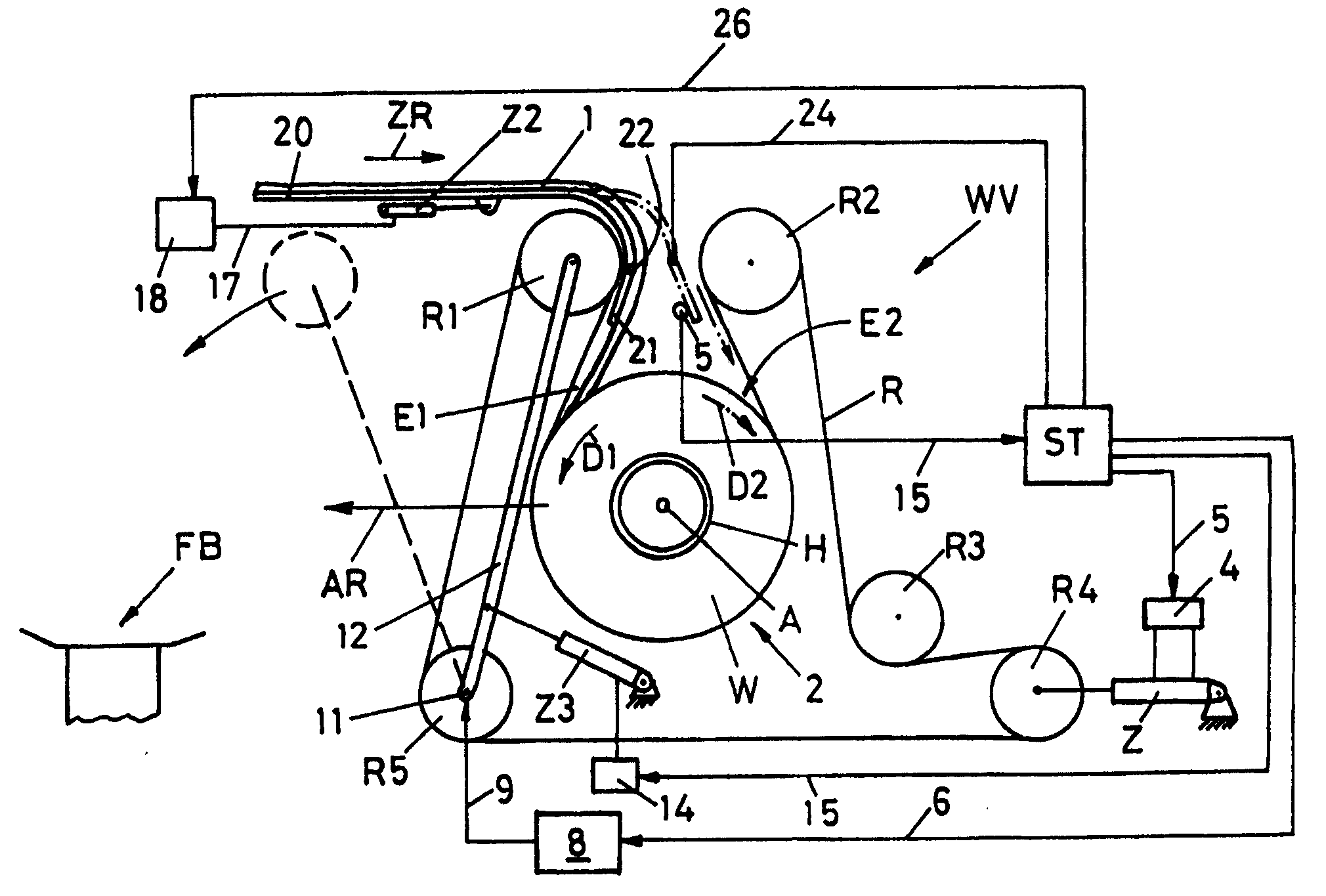
[0018] Figure 1 shows a winding device WV with a belt R guided by guide pulleys R1-R5. The belt forms a loop 2 between the guide pulleys R1, R2, in which the roll W of wound cloth is formed. The fabric 1 is guided between two guide rollers R1 and R2 and wound onto a bobbin H. As shown in FIG. The bobbin H is housed by a central disc (not shown) mounted transversely and fixedly and internally subjected to a subatmospheric pressure at least during the start of the winding process. Further details of this embodiment are described, for example, in EP-A1-799337.

[0019] As the diameter of the wound cloth roll W increases, so does the loop 2 . The belt R is under tension under the action of the rollers Z so that the wound cloth roll W is under pressure during winding by the belt R. The drum Z is controlled by a valve 4 which is controlled by means of a line 4 via a control device ST. Drive device 8 , which is activated via line 6 under the action of said control device ST, driv...


PUM


Abstract

The present invention relates to a lap winder assembly for producing wound lap rolls(W), comprising at least one guiding element(20,21) for feeding the lap web(1)to a winder(WV), wherein the lap web(1)is around a core(H) and connected to a driving device(8)which is reversible. The invention is directed to improve the present device and to realize the direction change of the winding direction of the wound lap rolls(W), so that, the guiding element(20,21)is movably set with respect to the winder(WV).

Description

technical field [0001] The invention relates to a device for producing wound cloth rolls, which has at least one guide element for feeding a fabric to a winding device, wherein the fabric is wound on a core and is connected to a reversible drive. Background technique [0002] EP-A1-799337 discloses a winding device for the production of wound cloth rolls having a wound cloth roll formed in a continuously rotating belt loop. In the central part of the ring there is a fixed and rotatably fixed bobbin (core) on which the fabric is conveyed through guide plates. In the embodiment of EP '337 as shown in Fig. 1, the fabric is fed through a guide plate to a winding device provided at its end with an arcuate guide surface through which the fabric is fed to a rotating Downstream of the first pulley between the belt and the bobbin. The direction of winding is counterclockwise in the illustrated embodiment. [0003] After the wound cloth roll has been produced, it is conveyed by osc...

Claims


Application Information

Patent Timeline
Patent Type & Authority Patents(China)
IPC IPC(8): B65H23/32B65H67/00D01G27/00D01G31/00
CPCD01G31/006D01G27/00
Inventor A・鲁施A・克莱纳
Owner MASCHINENFABRIK RIETER AG
Why Eureka
Try Eureka