Eureka AIR delivers breakthrough ideas for toughest innovation challenges, trusted by R&D personnel around the world.

Decimation filtering apparatus and method

A technology of decimation filtering and decimation filter, which is applied in the direction of impedance network, analog-to-digital converter, digital technology network, etc., and can solve problems such as difficult to realize manufacturing devices

Inactive Publication Date: 2001-02-28
SAMSUNG ELECTRONICS CO LTD
View PDF0 Cites 11 Cited by
  • Summary
  • Abstract
  • Description
  • Claims
  • Application Information

AI Technical Summary

Problems solved by technology

Therefore, it is also difficult to realize the fabrication of the second prior art device

Method used


Image

  • Decimation filtering apparatus and method
  • Decimation filtering apparatus and method
  • Decimation filtering apparatus and method

Examples


example 2

[0117] For IS-95, the desired sampling frequency is Fs=49.152Msps, which is 40 times the chip rate of 1.2288M chips per second. Assuming that the desired output rate of the PFIR filter 57 is twice this chip rate, it is set to D=20. The passband and stopband specifications of the overall decimation filter are determined from the passband and stopband specifications of commercially available analog IF filters being used in IS-95 systems. Specifically, the filter disclosed by Sawket Company's 97 annual data sheet No. 854550-1 (Part Number 854550-1 Data Sheet, Sawket Inc., 1997) is considered to have the following technical indicators:

[0118] Passband edge: 630kHz from carrier

[0119] Pass band ripple: 0.7dB...(19)

[0120] Stopband: 35dB attenuation at 750kHz from carrier

[0121] 50dB attenuation at 900kHz from carrier

[0122] In normalized frequency, the technical indicators are:

[0123] Passband: f ∈ [0, 0.0128]

[0124] Stopband: f ∈ [0.0153, 0.5]...(20)

[0125] ...


PUM


Abstract

A decimation filtering apparatus using interpolated second order polynomials compensates for a droop caused by a CIC (Cascaded Integrator-Comb) filter (51). The decimation filter includes a CIC decimation filter (51) for decimation filtering the sampling signal to downconvert a sampling signal; an ISOP filter (53) for monotonically increasing an output of the CIC decimation filter (51) to compensate for a passband droop caused by the CIC decimation filter (51); a multistage halfband filter (55) including at least one modified halfband filter for 1 / 2 decimating a signal output from the ISOP filter (53), the multistage halfband filter (55) decimating the signal output from the ISOP filter (53) to downconvert the signal; and a programmable FIR (Finite Impulse Response) filter (57) for compensating for a passband droop of a signal output from the multistage halfband filter (55).

Description

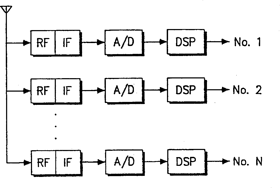
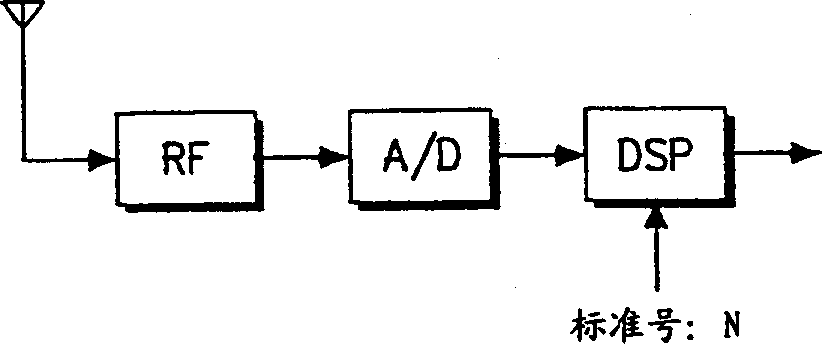
Background of the invention [0001] 1. field of invention [0002] The present invention relates to a decimation filter device and method, and more particularly to a decimation filter device and method using an interpolating quadratic polynomial (ISOP). [0003] 2. Related technical description [0004] With the development of bandwidth analog-to-digital conversion (ADC) technology and fast digital signal processing (DSP) technology, it has become possible to perform processing and digital signal processing in the IF (intermediate frequency) band and baseband. A software defined radio system refers to a system that starts digital signal processing in the IR or RF (Radio Frequency) band. [0005] With the programmability of digital signal processing, the software radio system can effectively support multi-band, multi-mode and multi-function communication. For example, having figure 1 The base station of the AMPS (Advanced Mobile Phone Service) mobile communication system o...

Claims


Application Information

Patent Timeline
IPC IPC(8): H03H17/00H03H17/02H03H17/04H03H17/06H03M1/16
CPCH03H17/0671H03M1/16
Inventor 吴赫俊李勇勋金善彬崔镇圭
Owner SAMSUNG ELECTRONICS CO LTD
Why Eureka
Eureka Blog
Learn More