
Open spinning appst. having air static force radial bearing for spinning rotor

A technology of starting spinning and radial bearing, applied in air cushion bearings, free-end spinning machines, bearings, etc., it can solve the problems of aerostatic radial bearings being damaged and unusable, and achieve high mechanical bearing capacity and small friction. Coefficient, the effect of reducing negative effects

Inactive Publication Date: 2006-10-04
RIETER INGOLSTADT SPINNEREIMASCHENBAU AG
View PDF2 Cites 0 Cited by
  • Summary
  • Abstract
  • Description
  • Claims
  • Application Information

AI Technical Summary

Problems solved by technology

or the aerostatic radial bearing has been damaged on contact and cannot be used

Method used


Image

  • Open spinning appst. having air static force radial bearing for spinning rotor
  • Open spinning appst. having air static force radial bearing for spinning rotor
  • Open spinning appst. having air static force radial bearing for spinning rotor

Examples


Embodiment Construction

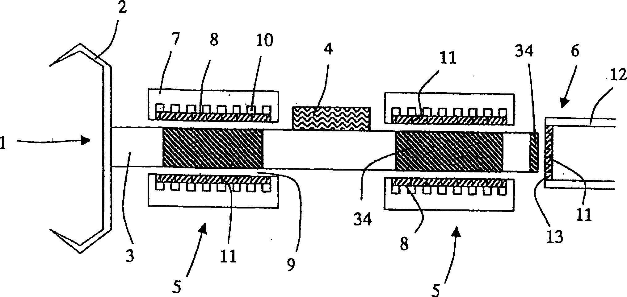
[0020] figure 1 Shown is a spinning rotor 1 with a rotor disk 2 and a shaft 3 for an open-end spinning device. The shaft 3 is moved in rotation by a tangential drive belt 4 running on the shaft 3 . The shaft 3 is radially supported by two identical radial bearings 5 ​​, while the axial support of one end face is realized by an axial bearing 6 mounted on the end of the shaft 3 opposite to the rotor disk 2 .

[0021] exist figure 1 In the illustrated embodiment of the rotor shaft bearing, the axial forces acting in the direction of the axial bearing 6 are transmitted by a slightly inclined drive belt 4 running on the shaft 3 . Wherein the transmission belt 4 is not at an angle of 90° to the axis of the shaft 3 but runs at a very small angle. exist figure 1 The rotation of the shaft 3 shown in for example enters the drawing plane with its top and turns outwards from the drawing plane with its bottom part, like this, the drive belt 4 that is straight to the drawing plane direc...


PUM

PropertyMeasurementUnit
diameteraaaaaaaaaa

Abstract

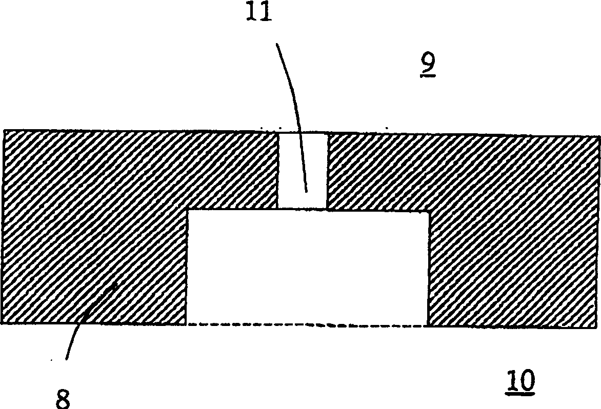
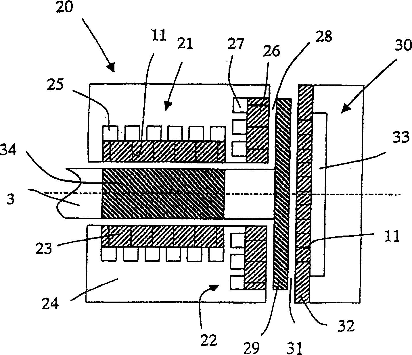
The invention concerns an open-end spinning apparatus with a spin-rotor, the shaft of which is supported by an aerostatic, radial bearing with an air gap between the bearing assembly and the shaft. The construction material for the bearing surface of the spin-rotor and / or the bearing surface of the radial bearing is polyimide or aramid.

Description

technical field [0001] The invention relates to an open-end spinning device with a spinning rotor whose shaft passes through an aerostatic radial bearing with a gap provided between the bearing device and the shaft and the used aerostatic radial bearing. Bearings support it in the longitudinal direction. Background technique [0002] In a known open-end spinning device (JP57-27212), the shaft of the spinning rotor is always supported in a radial bearing on its front and rear ends. The compressed air coming from the rear, which has passed through the bearing surface of the radial bearing, is guided through holes into the interspace between the bearing surface of the radial bearing and the bearing surface of the spinning rotor. During normal operation, the aerostatic bearing enables a wear-free and low-friction spinning rotor construction. [0003] However, in the course of the rotation of the spinning device at the start, there are occasions when uneven operating conditions...

Claims


Application Information

Patent Timeline
Patent Type & Authority Patents(China)
IPC IPC(8): D01H4/12F16C32/06F16C33/20
CPCF16C2340/18F16C32/0685F16C32/0692F16C32/0622D01H4/12F16C33/201
Inventor R·潘恩B·斯汤
Owner RIETER INGOLSTADT SPINNEREIMASCHENBAU AG
Learn More