Radio Communication apparatus and method
A wireless communication device and wireless communication technology, applied in radio transmission systems, communication between multiple stations, polarization/direction diversity, etc., can solve problems such as signal interference
- Summary
- Abstract
- Description
- Claims
- Application Information
AI Technical Summary
Problems solved by technology
Method used
Image
Examples
no. 1 example
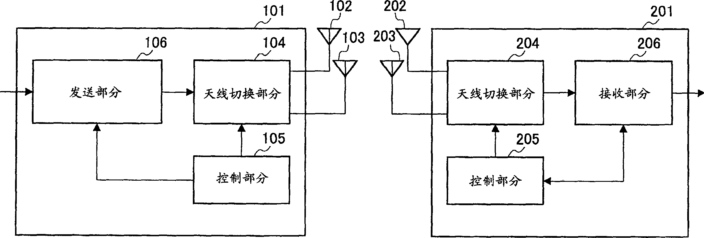
[0025] This embodiment explains the case where the polarization used in transmission and reception is the same and the communication speeds before modulation and after demodulation are also the same in a wireless communication system according to the present invention. figure 1 is a block diagram illustrating configurations of a radio base station and a radio terminal device according to the first embodiment of the present invention.
[0026] exist figure 1 Among them, a radio base station 101 has antennas 102 and 103 , an antenna switching section 104 , a control section 105 , and a transmission section 106 . Wireless terminal device 201 has antennas 202 and 203 , antenna switching section 204 , control section 205 , and receiving section 206 .
[0027] Wireless signals of different polarizations are transmitted using the antennas 102 and 103 . Similarly, antennas 202 and 203 are used to transmit wireless signals of different polarizations.
[0028] The antennas 102 and 20...
no. 2 example
[0053] This embodiment explains that in the wireless communication system according to the present invention, different polarizations are used between the downlink in which the wireless base station transmits signals to the wireless terminal device and the uplink in which the wireless terminal device transmits signals to the wireless base station, and the A situation where the polarization used in transmission and reception varies with the communication speed. Figure 4 is a block diagram illustrating configurations of a radio base station and a radio terminal device according to a second embodiment of the present invention. Additionally, for figure 1 Parts having the same functions in , are assigned the same reference numerals to omit their special descriptions.
[0054] Figure 4 The radio base station 301 in has a control section 302 , a reception section 303 and an antenna switching section 304 , while the radio terminal device 401 has a control section 402 , a transmiss...
no. 3 example
[0075] This embodiment illustrates the case where the polarization used in communication varies with the type of use in the wireless communication system according to the present invention. In particular, a case where a user uses two usage types, voice communication and data communication, will be described.
[0076] Figure 5 is a block diagram illustrating configurations of a wireless base station and a wireless terminal device according to a third embodiment of the present invention. Additionally, with figure 1 Parts with the same functions are assigned the same reference numerals to omit special explanations thereof.
[0077] Figure 5 The wireless base station 501 in has a control section 502, a transmission section 503, and an antenna switching section 504, performs communication using different polarization methods between communications having different transmission conditions such as voice communication and data communication, and in this respect, the difference A...
PUM
 Abstract
Description
Claims
Application Information
 - R&D
- Intellectual Property
- Life Sciences
- Materials
- Tech Scout
- Unparalleled Data Quality
- Higher Quality Content
- 60% Fewer Hallucinations
Browse by: Latest US Patents, China's latest patents, Technical Efficacy Thesaurus, Application Domain, Technology Topic, Popular Technical Reports.
© 2025 PatSnap. All rights reserved.Legal|Privacy policy|Modern Slavery Act Transparency Statement|Sitemap|About US| Contact US: help@patsnap.com


