
Memory card

Active Publication Date: 2007-03-01
RENESAS ELECTRONICS CORP
View PDF6 Cites 28 Cited by
  • Summary
  • Abstract
  • Description
  • Claims
  • Application Information

AI Technical Summary

Benefits of technology

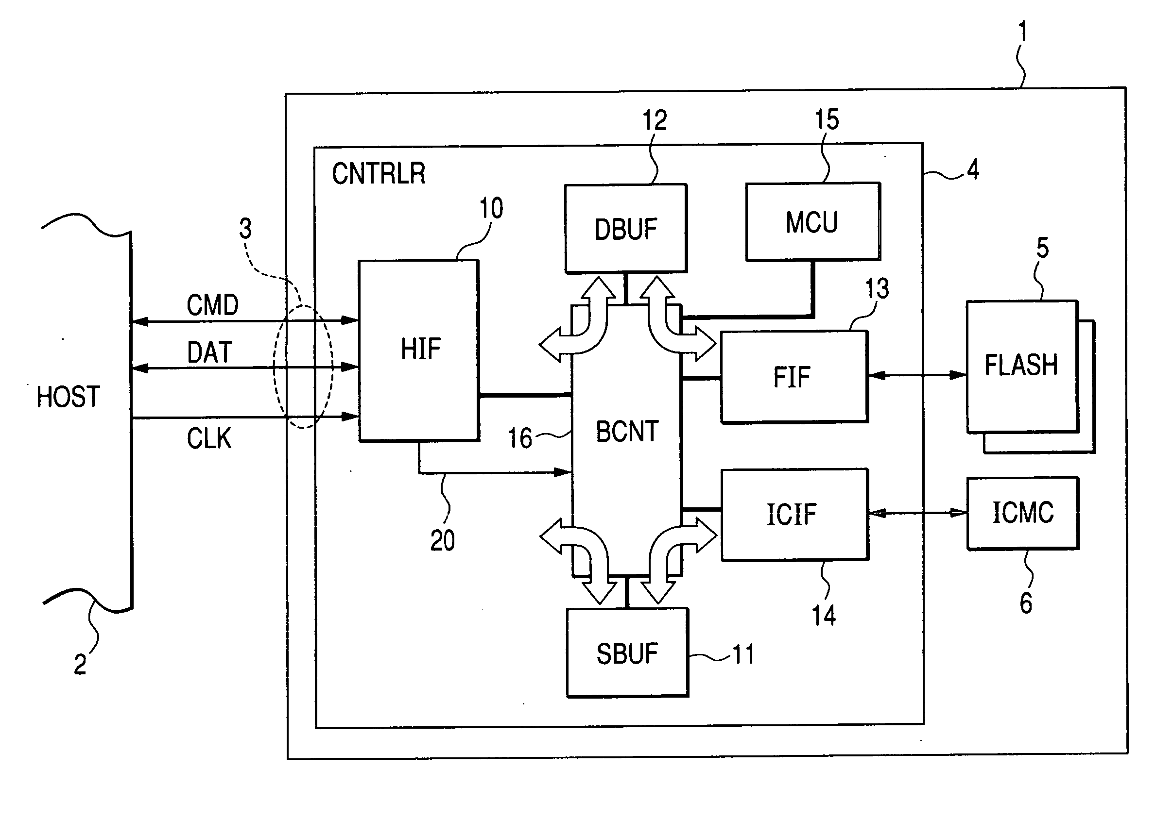
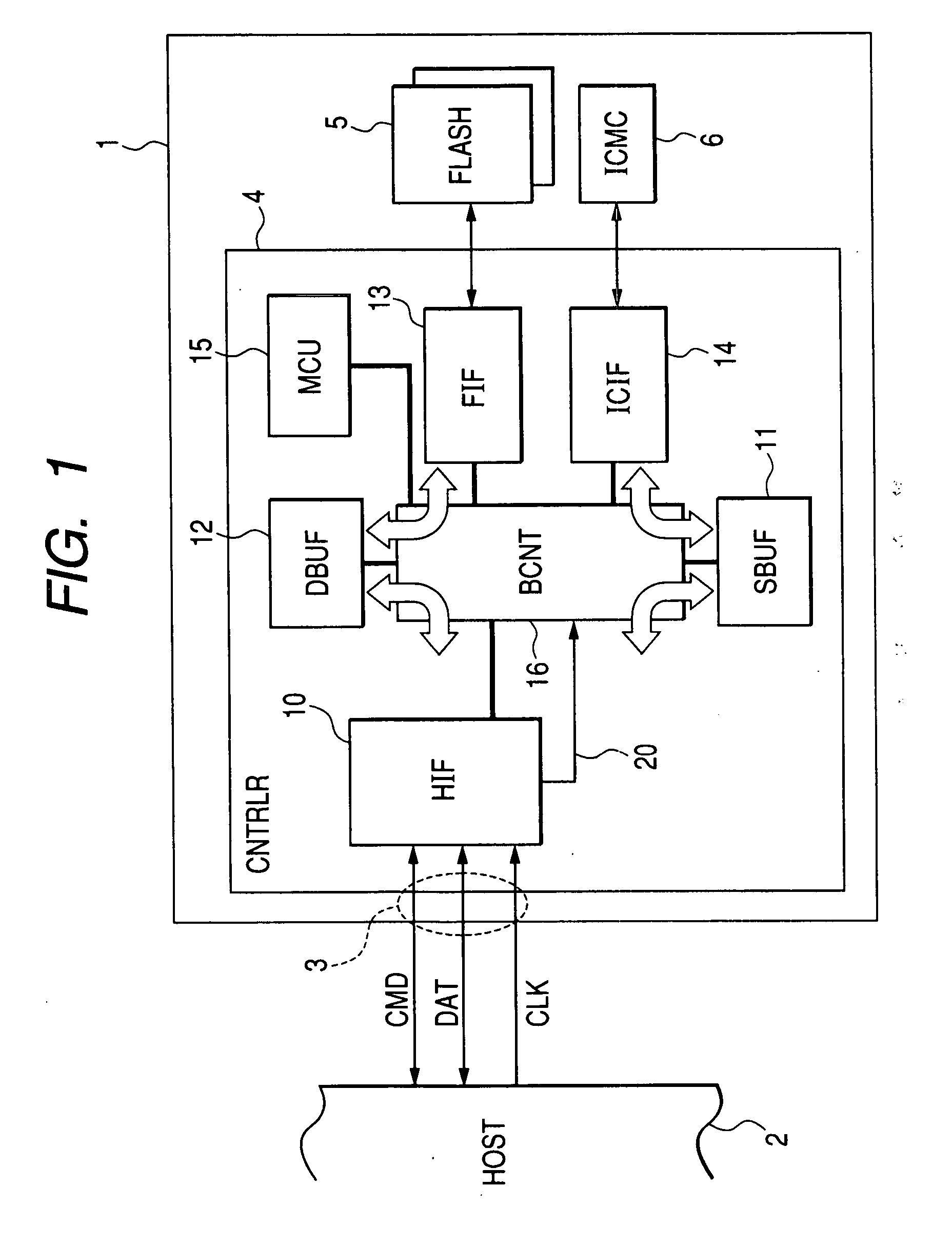
[0020] In a fifth aspect of the present invention, the interface controller further comprises a host interface (10) and a microcomputer (15). The host interface gives an interrupt request to the microcomputer in response to the inputting of a command (W-SEC, R-SEC, MC-CMD). The microcomputer executes an interrupt process corresponding to a type of the command in response to the interrupt request. When the inputted command is accompanied by the first command (C-APDU) for a data process, the microcomputer instructs the da

Problems solved by technology

Because the microcomputer chip for IC card inherently performs heavy-load data processes such as data encryption/decryption processes, an authentication process, and the like, when the memory card receives a command for IC card, the microcomputer chip may occasionally require a long time to perform a data process responding thereto.
When the speed of communication between the microcomputer chip for IC card and the controller chip is low or when large-capacity data is transmitted, the communication time is long so that a

Method used


Image

  • Memory card
  • Memory card
  • Memory card

Examples


first embodiment

of Buffer Control

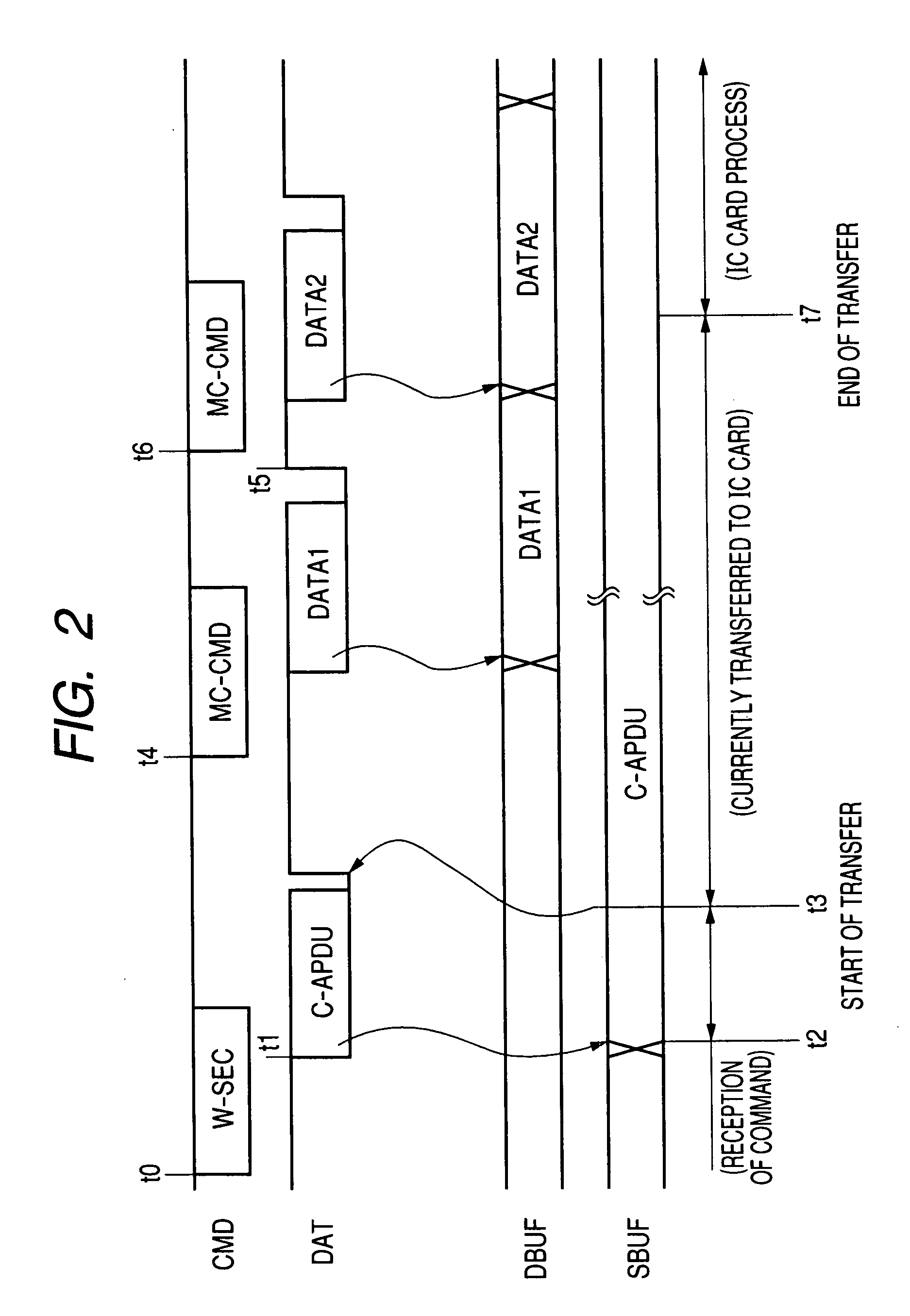
[0078] A description will be given to a first embodiment of the control of the secure buffer 11 and the data buffer 12 each described above. The host interface 10 determines the type of the command supplied from the host device 2 and gives the buffer indicating signal 20 in accordance with the result of the determination to the buffer controller 16. The buffer indicating signal 20 is a signal indicating which one of the secure buffer 11 and the data buffer 12 is to be used. In the case where the write secure control command is supplied, the buffer controller 16 stores the IC card command inputted together with the write secure command from the data I / O terminal DAT in the secure buffer 11. Upon completing the storage thereof in the secure buffer 11, the buffer controller 16 releases the notification of a busy state by causing the host interface 10 to shift the state of the data I / O terminal DAT from the LOW level to the HIGH level. Thereafter, when the host interfac...

second embodiment

of Buffer Control

[0089] A description will be given to a second embodiment of the control of the secure buffer 11 and the data buffer 12. FIG. 6 shows a memory card 1B to which the second embodiment of buffer control has been applied. The second embodiment of buffer control is different from the first embodiment of buffer control of FIG. 1 in the following point. That is, a buffer controller 16B uses the data buffer 12 described above for interfacing with the host device 2 via the external interface terminals 3 described above, internally transfers the IC card command to be supplied to the IC card chip 6 described above from the data buffer 12 to the secure buffer 11, and transfers the IC card response received by the security buffer 11 from the IC card interface 14 to the data buffer 12.

[0090] For example, the host interface 10 determines the type of the command supplied from the host device 2 and gives the buffer indicating signal 20 in accordance with the result of the determina...

third embodiment

of Buffer Control

[0093] A description will be given to a third embodiment of the control of the secure buffer 11 and the data buffer 12. FIG. 8 shows a memory card 1C to which the third embodiment of buffer control has been applied. The third embodiment of buffer control is different from the first embodiment of buffer control of FIG. 1 in the following point. That is, in the embodiments of buffer control described thus far, each of the data buffer 12 and the secure buffer 11 is a predetermined specific buffer. In FIG. 8, by contrast, two buffers 11C and 12C can be interchangeably allocated to the data buffer and to the secure buffer. At this time, a buffer controller 16C has a flag FLGb showing which one of the data buffer and the secure buffer the buffer 11C as one of the two buffers is allocated to and a flag FLGa showing which one of the data buffer and the secure buffer the buffer 12C as the other of the two buffers is allocated to. Each of the flags FLGa and FLGb has a secure ...


PUM


Abstract

A memory card has external interface terminals, an interface controller connected to each of the terminals, a rewritable nonvolatile memory connected to the interface controller, and a data processor connected to the interface controller. The interface controller can perform an operation based on another command supplied from the outside in parallel with the operations of transferring a command for a data process supplied from the outside to the data processor and operating it. The interface controller has plural buffers and, after completely inputting the command for a data process from an outside to a first buffer of the plural buffers, allows data related to the other command supplied from the outside to be inputted to a second buffer of the plural buffers. The memory card can receive a command data and data to be processed subsequently from the outside without the need of waiting for the completion of the communication process between the data processor and the interface controller.

Description

CROSS-REFERENCE TO RELATED APPLICATION [0001] The present application claims priority from Japanese patent application No. 2005-242568 filed on Aug. 24, 2005, the content of which is hereby incorporated by reference into this application. BACKGROUND OF THE INVENTION [0002] The present invention relates to a memory card having a security function performed by using a data processor and to a technology which is useful when applied to a memory card having, e.g., a microcomputer for IC card mounted thereon together with a flash memory or the like. [0003] Each of Patent Document 1 and Patent Document 2 discloses a memory card with a security function which comprises a flash memory chip, a microcomputer chip for IC card, and a controller chip. The microcomputer for IC card performs a security process. The controller chip controls access to the flash memory chip and to the IC card chip and the like in response to a request from a host. And Patent Document 3 discloses a memory card having a...

Claims


Application Information

Patent Timeline
IPC IPC(8): G06K19/06
CPCG06F13/4239G11C7/20G06K19/077
Inventor YOSHIDA, SATOSHIMIZUSHIMA, NAGAMASAASARI, SHINSUKEKURAKATA, SHIGEOOBATA, MAKOTO
Owner RENESAS ELECTRONICS CORP
Learn More