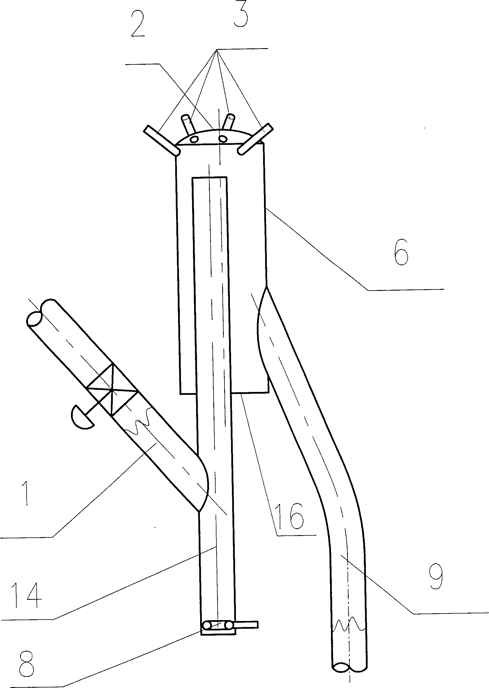
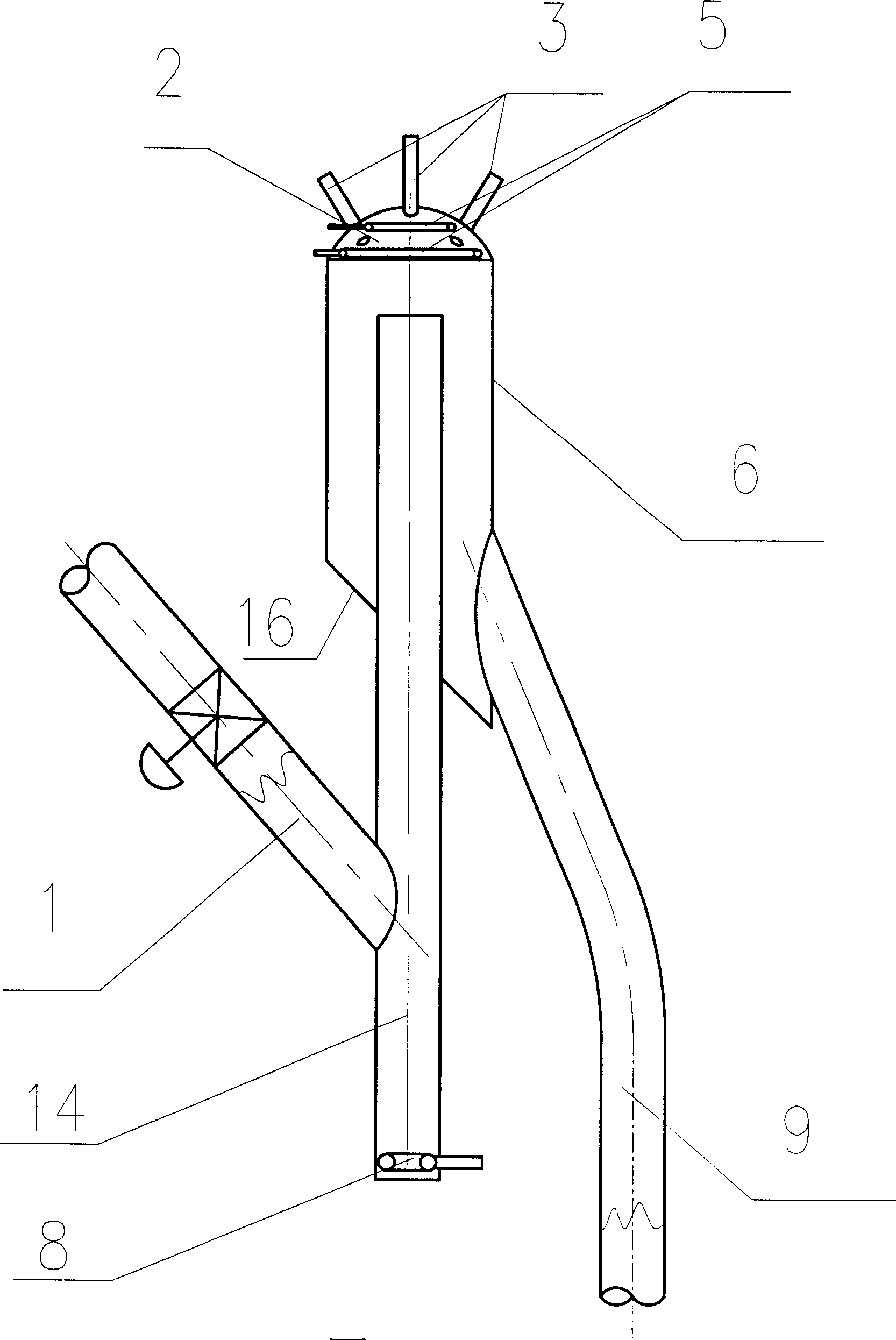
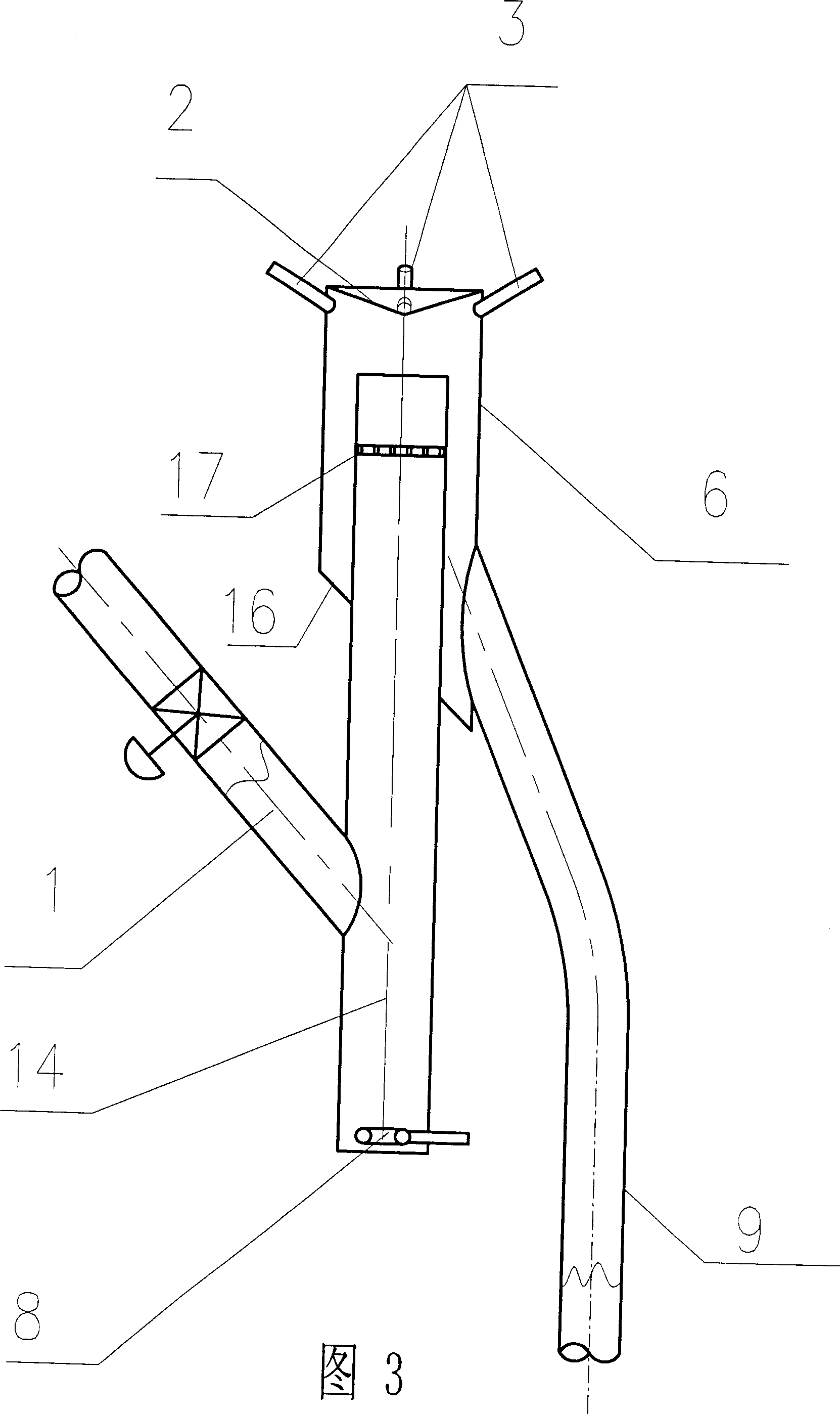
Descending catalytic cracking reactor
A catalytic cracking and reactor technology, applied in catalytic cracking, cracking, petroleum industry, etc., can solve problems such as back-mixing equipment, low conversion rate of hydrocarbon oil raw materials, coking tendency, etc., to overcome serious back-mixing and improve atomization effect , the effect of uniform particle size
- Summary
- Abstract
- Description
- Claims
- Application Information
AI Technical Summary
Problems solved by technology
Method used
Image
Examples
Embodiment 1
[0052] This example illustrates: the test results obtained under conventional catalytic cracking reaction conditions using the down-flow reactor provided by the present invention.
[0053] The structural form of the downcomer reactor used in this embodiment is as follows figure 1 shown.
[0054] The raw material oil used in the embodiment, the catalyst and the test procedure are all the same as in Comparative Example 1, and the main operating conditions, product distribution and main product properties are shown in Table 3.
[0055] As can be seen from Table 3, compared with the comparative example, the heavy oil content in the product of the embodiment has decreased by more than 10 percent, the light hydrocarbon yield has increased by more than 10 percent, the dry gas yield and the comparative example are basically the same, and the coke Although the absolute yield has risen, this is because more heavy oil is converted, if calculated by relative yield (dry gas yield / heavy o...
Embodiment 2
[0057] This embodiment illustrates: adopt the descending type reactor provided by the present invention to obtain under harsher reaction condition test result.
[0058] The structure of the down-flow reactor used in this embodiment is as follows Figure 7 shown.
[0059] The raw material oil used in the embodiment, the catalyst and the test procedure are all the same as in Comparative Example 2, and the main operating conditions, product distribution and main product properties are shown in Table 4.
[0060] As can be seen from Table 4, compared with the comparative example, the heavy oil content in the product of the embodiment has reduced by more than 8 percentage points, and the light hydrocarbon yield has increased by nearly 9 percentage points, while the dry gas yield and the coke yield and the relative The proportion is basically the same. The yield of propylene in the product increased by more than 3 percentage points. It can be seen that using the down-flow reactor ...
Embodiment 3
[0062] This embodiment illustrates: adopt the descending type reactor provided by the present invention to obtain under the reaction condition of high severity test result.
[0063] The structure of the down-flow reactor used in this embodiment is as follows Figure 11 shown.
[0064] The raw material oil used in the embodiment, the catalyst and the test procedure are all the same as in Comparative Example 3, and the main operating conditions, product distribution and main product properties are shown in Table 5.
[0065] As can be seen from Table 5, compared with the comparative example, the heavy oil content in the product of the embodiment has decreased by more than 6 percentage points, the ethylene yield and the propylene yield have all increased by more than 3 percentage points, and the productive rate of coke has decreased by nearly 1 percentage point. It can be seen that using the down-flow reactor provided by the present invention to convert hydrocarbon oil raw mater...
PUM
| Property | Measurement | Unit |
|---|---|---|
| density | aaaaa | aaaaa |
Abstract
Description
Claims
Application Information
 - R&D Engineer
- R&D Manager
- IP Professional
- Industry Leading Data Capabilities
- Powerful AI technology
- Patent DNA Extraction
Browse by: Latest US Patents, China's latest patents, Technical Efficacy Thesaurus, Application Domain, Technology Topic, Popular Technical Reports.
© 2024 PatSnap. All rights reserved.Legal|Privacy policy|Modern Slavery Act Transparency Statement|Sitemap|About US| Contact US: help@patsnap.com


