
Dispensing head for a squeeze dispenser

A sprayer and nozzle technology, applied in the field of mixing air and liquid to generate fine mist

Inactive Publication Date: 2006-05-10
EMSAR INC (US)
View PDF3 Cites 0 Cited by
  • Summary
  • Abstract
  • Description
  • Claims
  • Application Information

AI Technical Summary

Problems solved by technology

The disadvantage of this invention is that the knob is on the opposite side from the outlet opening

Method used


Image

  • Dispensing head for a squeeze dispenser
  • Dispensing head for a squeeze dispenser
  • Dispensing head for a squeeze dispenser

Examples


Embodiment Construction

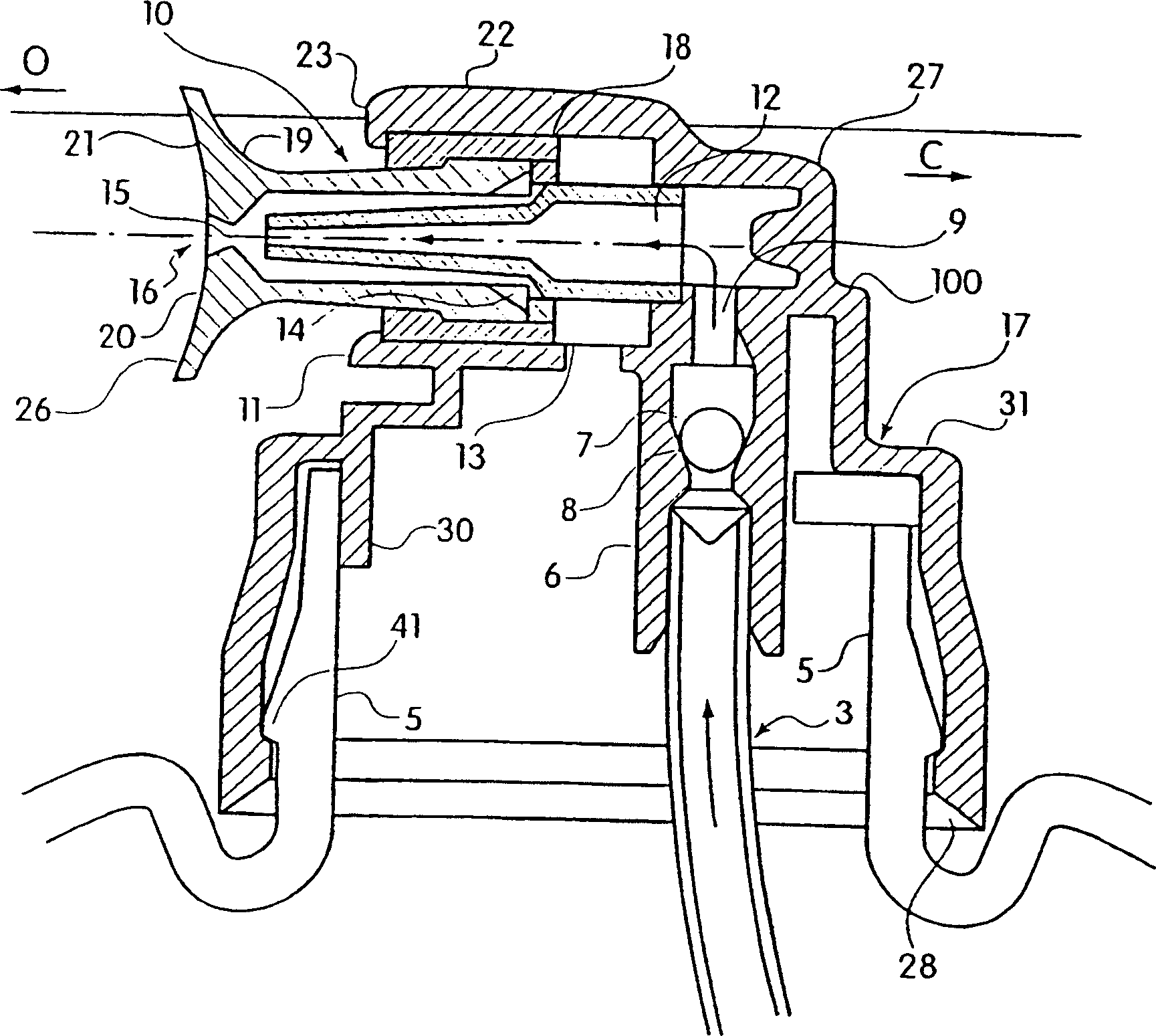
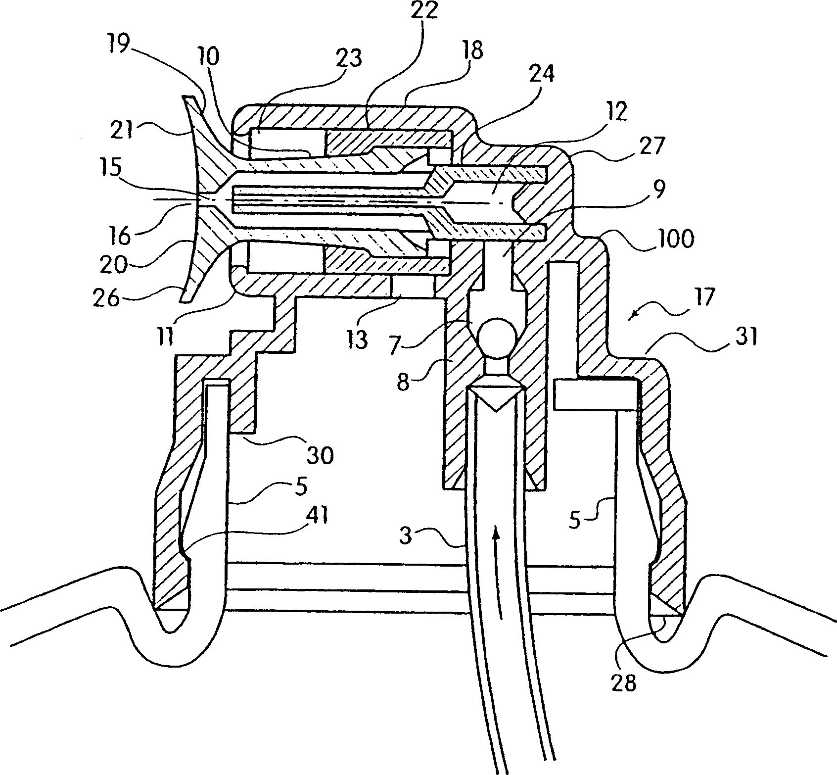
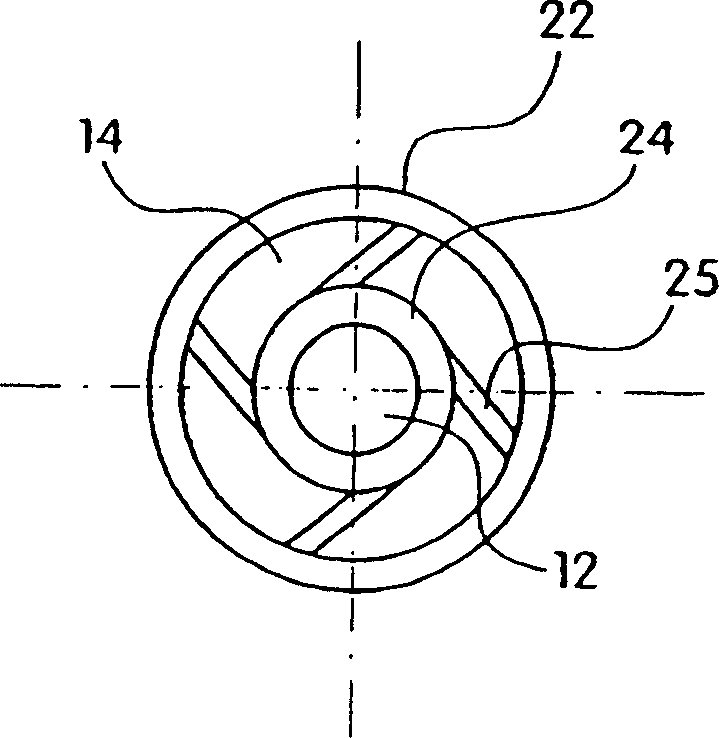
[0027] Such as figure 1 As shown, the spray dispensing system of the present invention comprises a squeeze bottle 1 (only a portion of which is shown) containing a quantity of liquid or other liquid material therein. The squeeze bottle can be made of any suitable resilient plastic known in the art.

[0028] A nebuliser housing or nebulizer body 17 is adapted to be mounted on the neck 5 of a bottle 1 by any means known to those skilled in the art. The spray dispensing device housing 17 includes a dip tube 3 sized such that the open bottom end of the dip tube 3 is positioned adjacent the bottom of the bottle when the spray device is mounted on the bottle.

[0029] The top end of the dip tube 3 is housed in the throttling line 6 of a ball check valve 7 . The throttle pipe 6 communicates with the dip tube 3 so that fluid can flow therethrough. The inner diameter of the throttling conduit 6 is smaller than the diameter of the ball 8 of the check ball valve 7 , so the ball 8 usua...


PUM


Abstract

A spray head (17) of a squeeze sprayer (1) is disclosed. The spray head (17) includes channels (12, 14) for directing the air and liquid streams to a mixing chamber (15) where the liquid is dispersed into droplets and sprayed from the nozzle (6) in the form of a mist. The device includes a valve (10) operated by a push-pull movement. When the valve (10) is closed, the liquid is isolated from the atmosphere, thereby preventing the liquid product from drying out or becoming contaminated.

Description

technical field [0001] This invention relates to a spray head for sprayers which are pressurized through the side of a squeeze container, and in particular to a spray head in which air and liquid mix to form a fine mist; wherein a push-pull valve arrangement is provided for dispensing when the sprayer is not in use. The liquid is sealed from the atmosphere. Background technique [0002] Although squeeze bottle sprayers have been used for many years, these sprayers were largely replaced by pressurized can spray systems for a long time. A squeeze bottle sprayer that has been used instead of a pressurized can is described in US Patent Nos. 5,183,186 and 5,318,205. These patents show a squeeze bottle sprayer in which an air channel and a product (ie liquid material) channel meet in a conical mixing chamber. In the device of this invention, due to the conical shape of the mixing chamber, the gas flow is at an angle to the liquid flow, causing turbulence in the liquid in the mix...

Claims


Application Information

Patent Timeline
Patent Type & Authority Patents(China)
IPC IPC(8): A62C11/00B65D83/00A62C31/02B05B7/08B05B11/04
CPCB05B11/043A62C11/00
Inventor R·S·舒尔茨
Owner EMSAR INC (US)
Learn More