
Electromagnetic induction device

An electromagnetic induction and coil technology, applied in the transformer/inductor shell, preventing/reducing unnecessary electric/magnetic influence, transformer/reactor installation/support/suspension, etc., can solve the problem of large size and long-term insulation Deterioration, local surface pressure increase, etc.

Inactive Publication Date: 2006-03-01
MITSUBISHI ELECTRIC CORP
View PDF0 Cites 0 Cited by
  • Summary
  • Abstract
  • Description
  • Claims
  • Application Information

AI Technical Summary

Problems solved by technology

[0005] Therefore, in the conventional transformer structure shown, since the horizontal members constituting the upper and lower end frames that hold the coil in the lateral length direction are arranged to be in contact with the coil main body side, there is a possibility that the magnetic field lines leaked from the high and low voltage coils are easily intruded and caused by This causes the disadvantage of high spurious loss
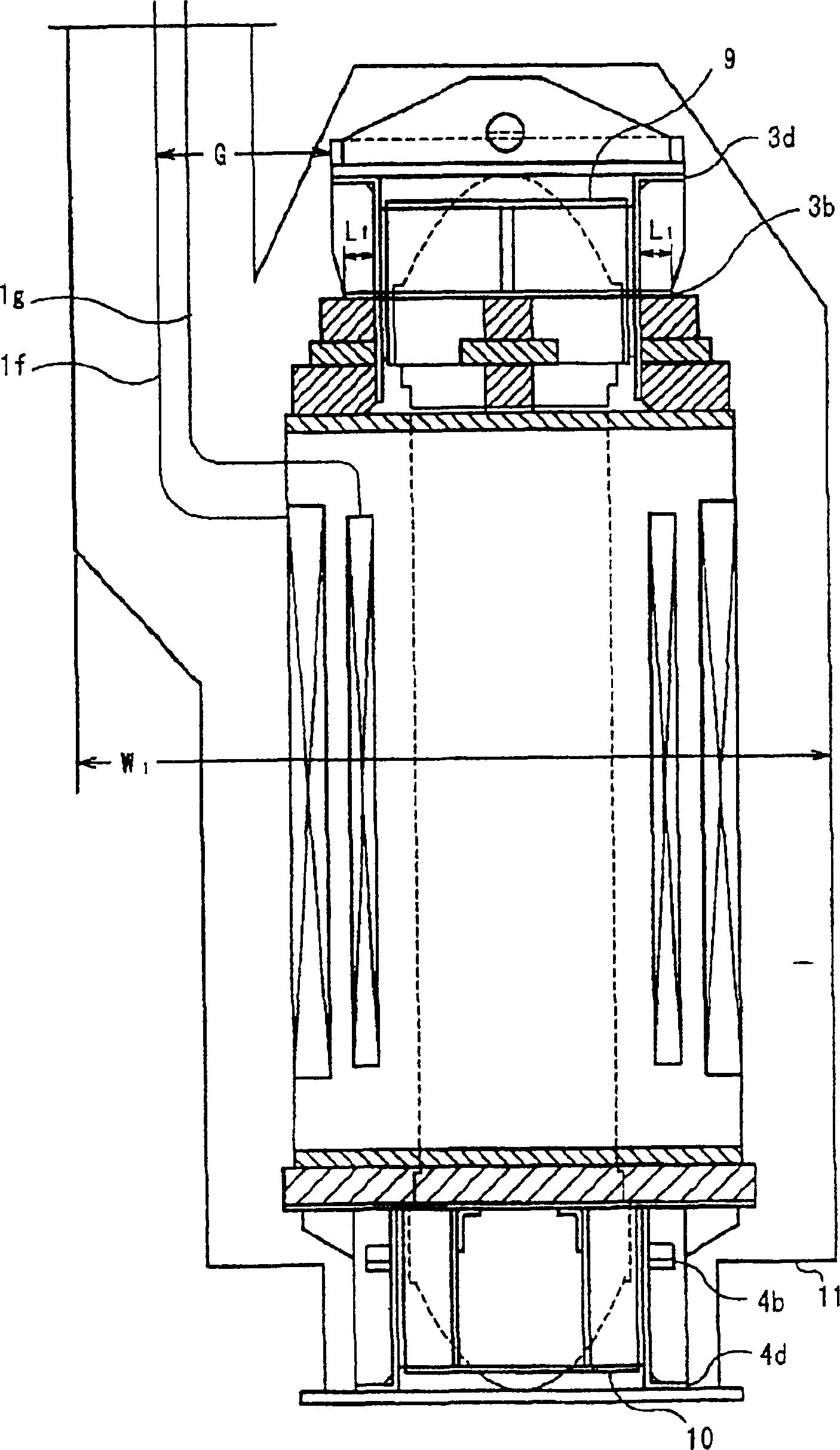
[0006] In addition, the lead-out wires 1g and 1f of the coil are curved because they are provided with an insulating distance G from the upper frame 31 made of a metal material. As a result, the width W of the coil barrel 11 is 2 larger size
And because the coil 1 is fastened axially through the coil compression bolt 12, the local surface pressure increases, which easily promotes the deterioration of the insulation over the years, and due to the aging of the insulating solid 6 and the coil supporting seat 7, the coil The compression bolt 12 is loose, and as a result, there is a disadvantage of corona discharge in the tiny gap between the bolt 12 and the upper frame 31

Method used


Image

  • Electromagnetic induction device
  • Electromagnetic induction device
  • Electromagnetic induction device

Examples


Embodiment Construction

[0016] Implementation form 1:

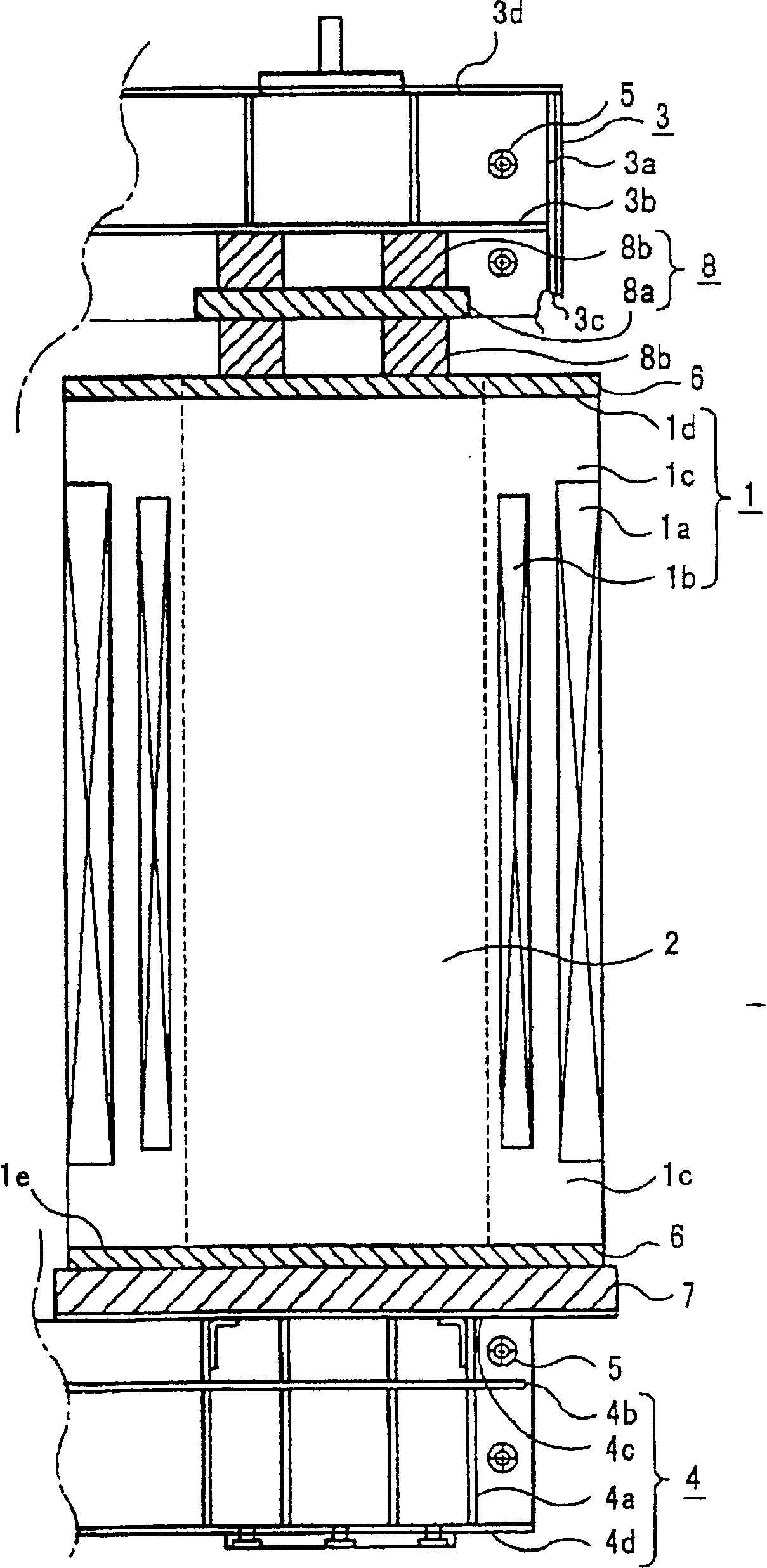
[0017] based on the following figure 1 , figure 2 Embodiment 1 of the present invention will be described. figure 1 It is a front view of the transformer, and only one of the three phases is shown. figure 2 for figure 1 side view.

[0018] In the figure, 1 is a coil, 1a is a high-voltage coil, 1b is a low-voltage coil, and 1c is an insulating block. These 1a, 1b, and 1c usually form an integrated coil 1. 1d is the upper end surface of the coil, and 1e is the lower end surface of the coil.

[0019] 2 is an iron core, 3 and 4 are upper and lower end frames, respectively, and the vertical members 3a and 4a and the horizontal members 3b, 3d, 4b and 4d are made of reinforcing materials, etc., which are not shown in the illustration. Moreover, the upper and lower end frames have end frame end faces 3c, 4c, and the above-mentioned horizontal parts 3b, 4b are set separately from the end frame end faces 3c, 4c. In addition, if figure 2 As sh...


PUM


Abstract

This invention is about a kind of electromagnetic induction machine, in which the horizontal member of the coil side of terminal rack used to hold coils is set as the terminal face leaving the terminal rack so as to reduce the magnetic flux leakage of the terminal frame part, decrease the stray loss, and prevent the corona discharge.

Description

technical field [0001] The invention relates to electromagnetic induction devices such as transformers and choke coils, and in particular to an axial fastening structure of coils. Background technique [0002] Figure 4 This is a front view showing the axial fastening structure of the coils of a conventional transformer, in which only one phase of the three-phase transformer is shown, and the other two phases are omitted due to the same structure. [0003] Figure 5 for Figure 4 side view. In the figure, 1 is a coil, which is composed of a high-voltage coil 1a, a low-voltage coil 1b, and an insulating block 1c that insulates the upper and lower ends of these coils 1a, 1b from the ground. 2 is the iron core, 31 and 41 are the upper end frame and the lower end frame, while the iron core 2 is firmly integrally fastened by the fastening bolt 5, it has the function of facing the electromagnetic force generated in the coil 1 and holding the coil 1. Features. The upper end fra...

Claims


Application Information

Patent Timeline
IPC IPC(8): H01F27/30H01F27/02H01F27/06H01F27/34
Inventor 辻洋
Owner MITSUBISHI ELECTRIC CORP
Learn More