
Methods and systems for installing cable and conduit in pipelines

A technology of pipelines and conduits, applied in the direction of cable installation, pipeline laying and repair, pipeline support, etc. in underground pipelines

Inactive Publication Date: 2006-01-25
SEMPRA BROADBAND
View PDF0 Cites 0 Cited by
  • Summary
  • Abstract
  • Description
  • Claims
  • Application Information

AI Technical Summary

Problems solved by technology

As a result, installing conduit or cables into gas pipelines presents a unique engineering challenge

Method used


Image

  • Methods and systems for installing cable and conduit in pipelines
  • Methods and systems for installing cable and conduit in pipelines
  • Methods and systems for installing cable and conduit in pipelines

Examples


Embodiment Construction

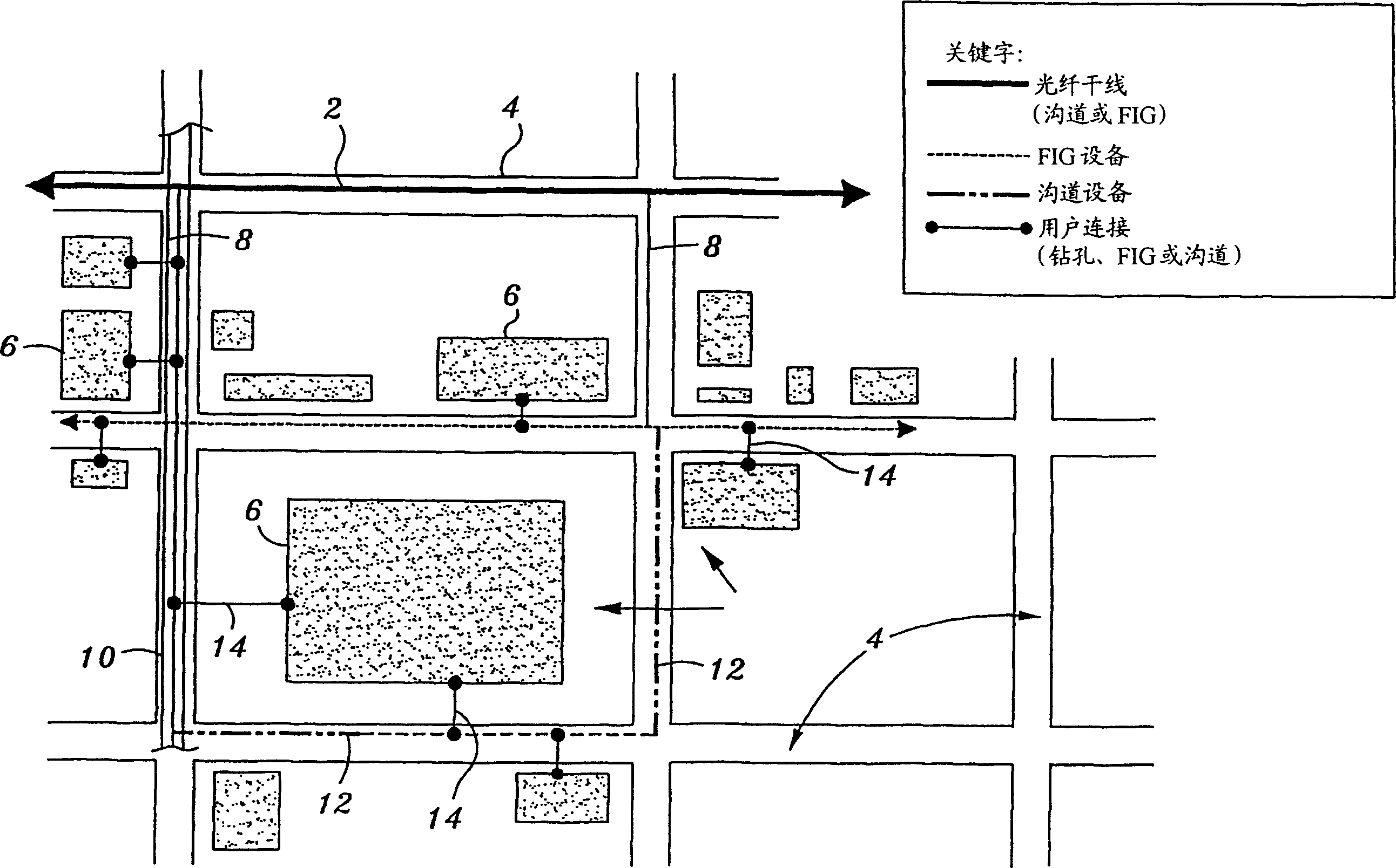
[0075] figure 1 A map or plan showing a portion of an urban area such as a city, town, college campus, etc. The main fiber optic trunk line 2 underlies one or more streets 4 . Various buildings 6 are scattered around the main fiber optic trunk line 2 . These buildings 6 may be individual properties, or the buildings 6 may be a campus that includes a variety of properties. Shown is a fiber optic conduit 8 carrying one or more bundles of fiber optic cables, branching off from the main fiber optic trunk 2 below the street 4 . The fiber optic conduit 8 is provided in a pressurized gas pipeline 10 located underground. The fiber optic conduit 8 is installed according to the method and apparatus described below.

[0076] still refer to figure 1 , in some streets 4 there is no existing pressurized gas pipeline 10, or the pipeline size or available capacity is not suitable for installing conduits or cables. In this case, the fiber optic conduit 8 is preferably installed in a conv...


PUM


Abstract

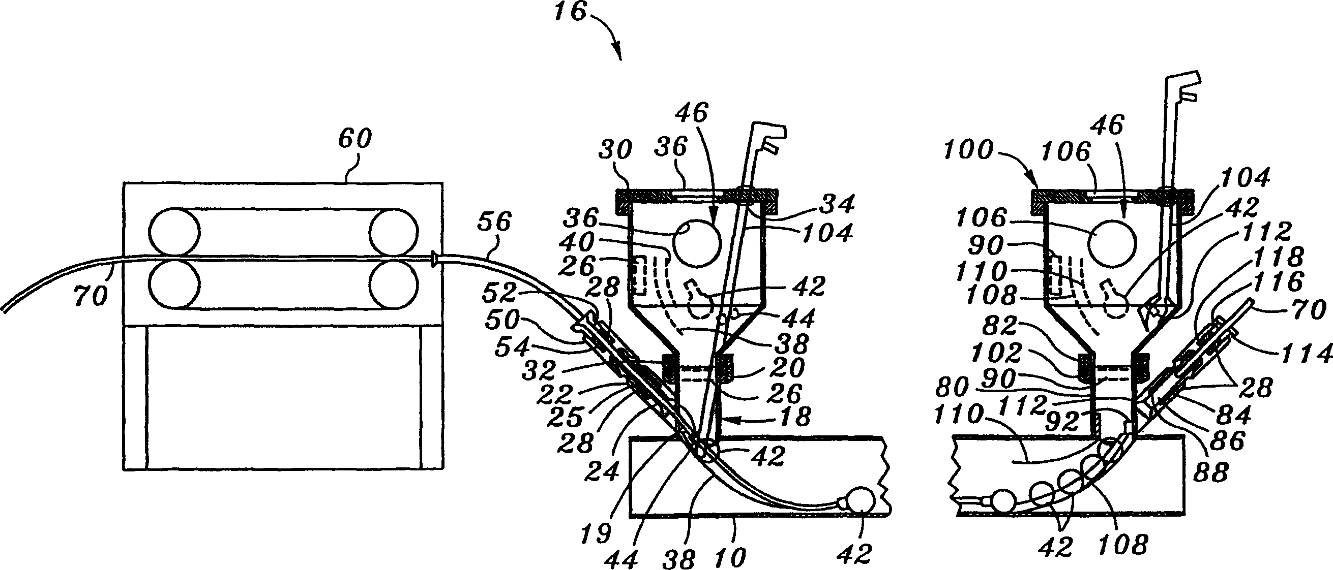
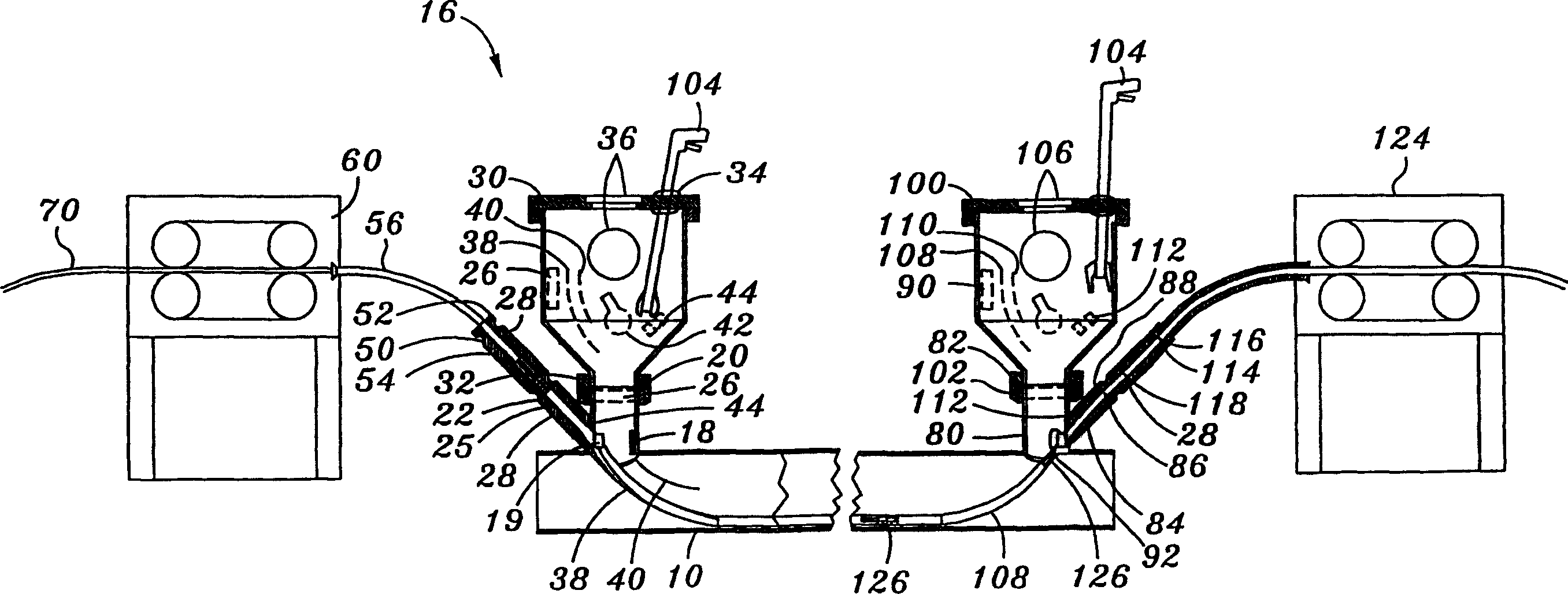
A method of introducing a fiber optic conduit into a pressurized gas pipeline includes the step of introducing a translating member into the pressurized gas pipeline via an entry port in a first drilling nipple attached to the pressurized gas pipeline. Tools are deployed within a first pressure lock housing attached to the first drilling nipple by using a first manipulator located in the first air lock housing. The duct rod is advanced within pressurized gas pipeline by a driving mechanism, until a second drilling nipple is reached. The translating member is attached to a fiber optic conduit. The duct rod and fiber optic conduit are then pulled back or pulled forward through the pressurized gas pipeline by the driving mechanism. A conduit is installed in a gas service line, to line the cable or conduit in a natural gas main pipeline to a telecommunications panel in a building.

Description

technical field [0001] The field of the invention is methods and systems for installing fiber optic cables or similar cables or conduits underground. The invention particularly relates to the installation of such cables or conduits within pressurized pipelines, such as natural gas pipelines or the like. Background technique [0002] In general, the explosion of Internet and telecommunication services has brought about a corresponding increase in the need to transmit ever increasing amounts of data over existing and new communication lines. However, existing copper-based communication lines have limited transmission capacity or bandwidth compared to optical cables. Ordinary copper wire also suffers from considerable wire harnessing problems compared to its fiber optic counterpart. Additional copper wires can be installed to increase the overall capacity of the communication or data network. Optical cables are now the first choice in the communications industry due to their...

Claims


Application Information

Patent Timeline
Patent Type & Authority Patents(China)
IPC IPC(8): B65H59/00F16K43/00F16L1/028G02B6/46F16L1/024F16L7/00H02G1/06H02G1/08H02G9/06
CPCF16L7/00H02G1/086G02B6/4459G02B6/502G02B6/508Y10T137/612Y10T137/6123Y10T137/4259Y10T137/8158Y10T137/6969Y10T137/0419G02B6/545G02B6/52G02B6/00
Inventor 斯科特·A·比尔斯罗伯斯·E·埃文斯罗纳德·D·哈默
Owner SEMPRA BROADBAND
Learn More