
Adiabatically following stark chirp light beam shaper

A technology of beam shaping and heat insulation, which is applied in optics, lasers, optical components, etc., can solve the problems of not providing practical devices, etc., and achieve the effects of amplification and shaping, high diffraction efficiency, and easy realization

Inactive Publication Date: 2005-11-16
SHANGHAI INST OF OPTICS & FINE MECHANICS CHINESE ACAD OF SCI
View PDF0 Cites 0 Cited by
  • Summary
  • Abstract
  • Description
  • Claims
  • Application Information

AI Technical Summary

Problems solved by technology

[0002] In the prior art, people such as Amitabb Joshi (Amitabb Joshi) control optical bistability in a three-level atomic system [Controlling optical bistability in three-level atomic system, Physical Review A67, 041801 (R) (2003)] discusses the theory and experiments on the control of bistability in three-level atomic systems, but does not provide a practical device for adiabatic following Stark chirp beam shaping

Method used


Image

  • Adiabatically following stark chirp light beam shaper
  • Adiabatically following stark chirp light beam shaper

Examples


Embodiment Construction

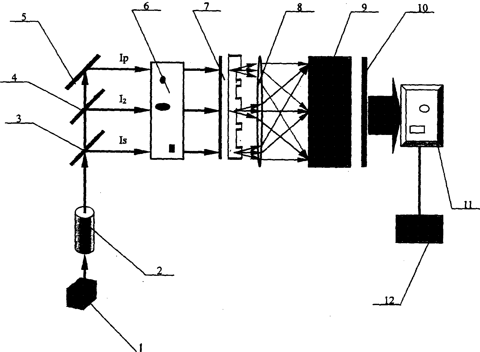
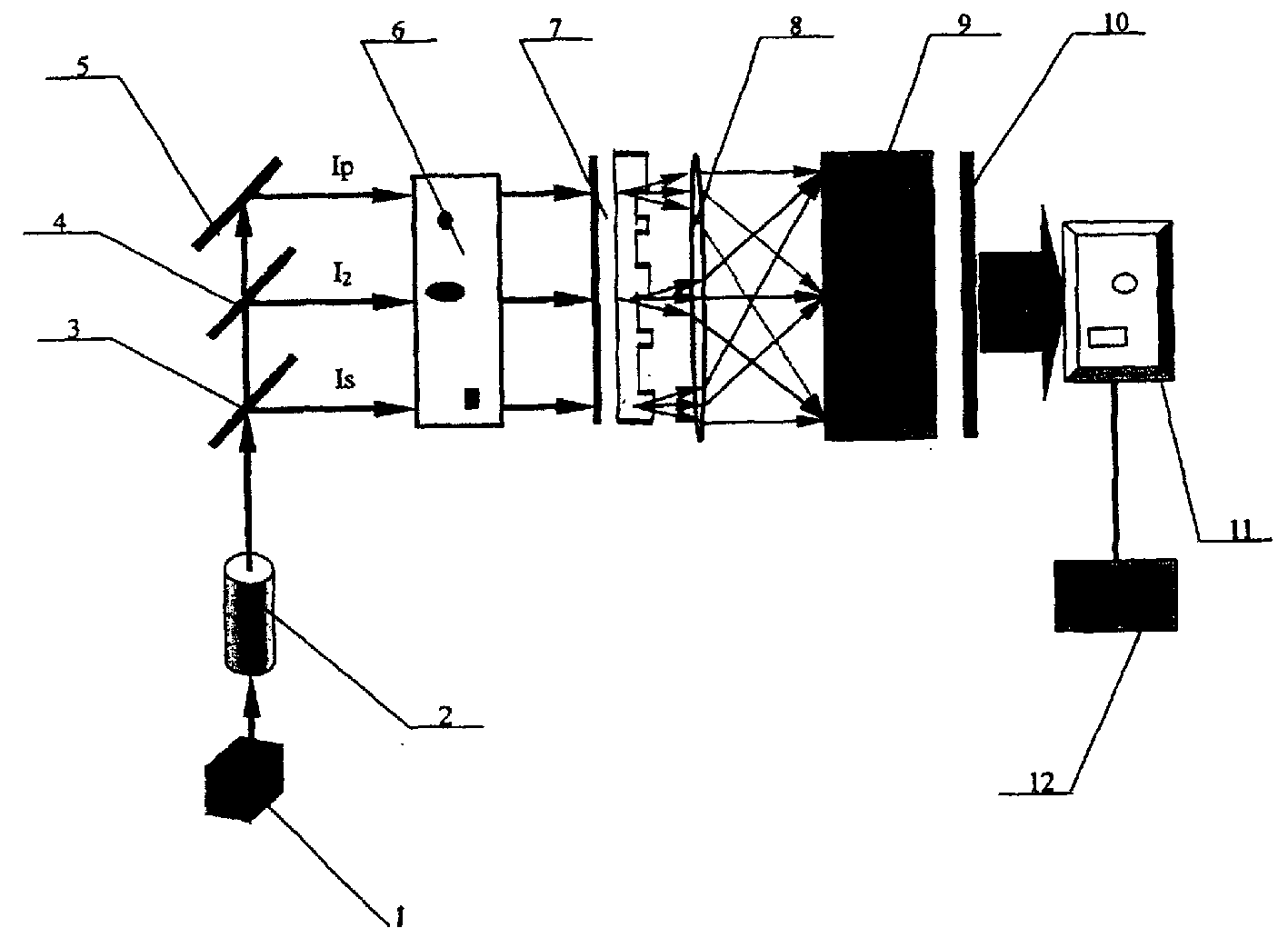
[0041] see first figure 1 , figure 1 It is a schematic structural diagram of the best embodiment of the adiabatic following Stark chirp beam shaping device of the present invention. It can be seen from the figure that the adiabatic following Stark chirping beam shaping device of the present invention includes the most core element as the binary optical element 7 , the electro-optic modulator 11, the pulse delay adjuster 6 is placed before the binary optical element 7, and before the pulse delay adjuster 6 is the anti-reflection polarizer 3, the semi-transparent and half-reflective polarizer 4 and the polarization total reflection multiplier The frequency crystal 5 is placed before the polarized total reflection frequency doubling crystal 5 and is the semi-transparent and semi-reflective polarizer 4, and before the semi-transparent and semi-reflective polarizer 4 is the anti-reflection polarizer 3, and before the anti-reflection polarizer 3 There is a laser light source 2 and ...


PUM


Abstract

The adiabatically following Stark chirp light beam shaper features that it consists of laser pumping source, laser light source, polarizing element with higher transmissibility and smaller reflectivity, half-reflecting and half-transmitting polarizing element, fully reflecting polarizing frequency doubling crystal, pulse delay regulator, binary optical element, lens, work medium, planar mirror, electro-optical modulator and receiver successively arranged in the light propagation direction.

Description

Technical field: [0001] The invention is an adiabatic following Stark chirp beam shaping device. Optical systems primarily used to shape beams in a non-linear manner in a controlled manner. Background technique: [0002] In the prior art, people such as Amitabb Joshi (Amitabb Joshi) control optical bistability in a three-level atomic system [Controlling optical bistability in three-level atomic system, Physical Review A67, 041801 (R) (2003)] discussed the theory and experiments on the control of bistability in three-level atomic systems, but did not provide a practical device for adiabatic following Stark chirp beam shaping. Invention content: [0003] The purpose of the present invention is to provide a device with the function of adiabatic following Stark chirp beam shaping, which uses Stark pulse and pump pulse partial overlap and delay to excite the working medium to generate Stark energy level shift to form a coherent superposition state , control the working medium...

Claims


Application Information

Patent Timeline
Patent Type & Authority Patents(China)
IPC IPC(8): G02B27/09H01S5/00
Inventor 金石琦龚尚庆
Owner SHANGHAI INST OF OPTICS & FINE MECHANICS CHINESE ACAD OF SCI
Learn More