
Heat Protector

A thermal protector and heating resistor technology, applied in thermal switches, thermal switch parts, contacts, etc., can solve the problem of inability to flow heating current, insufficient electrical contact stability between bimetal b and thermistor g, etc. problems, to achieve the effect of improving electrical contact stability, stable working characteristics, and load reduction

Inactive Publication Date: 2005-07-20
UCHIYA THERMOSTAT
View PDF1 Cites 0 Cited by
  • Summary
  • Abstract
  • Description
  • Claims
  • Application Information

AI Technical Summary

Problems solved by technology

In conventional thermal protectors, the surface on the highly extended side of the bimetal b is in contact with the resistive surface of the thermistor g, and the stability of the electrical contact between the bimetal b and the thermistor g is insufficient
Therefore, there is a possibility that an appropriate heating current cannot flow through the thermistor g after the bimetal b is reversed

Method used


Image

  • Heat Protector
  • Heat Protector
  • Heat Protector

Examples


Embodiment Construction

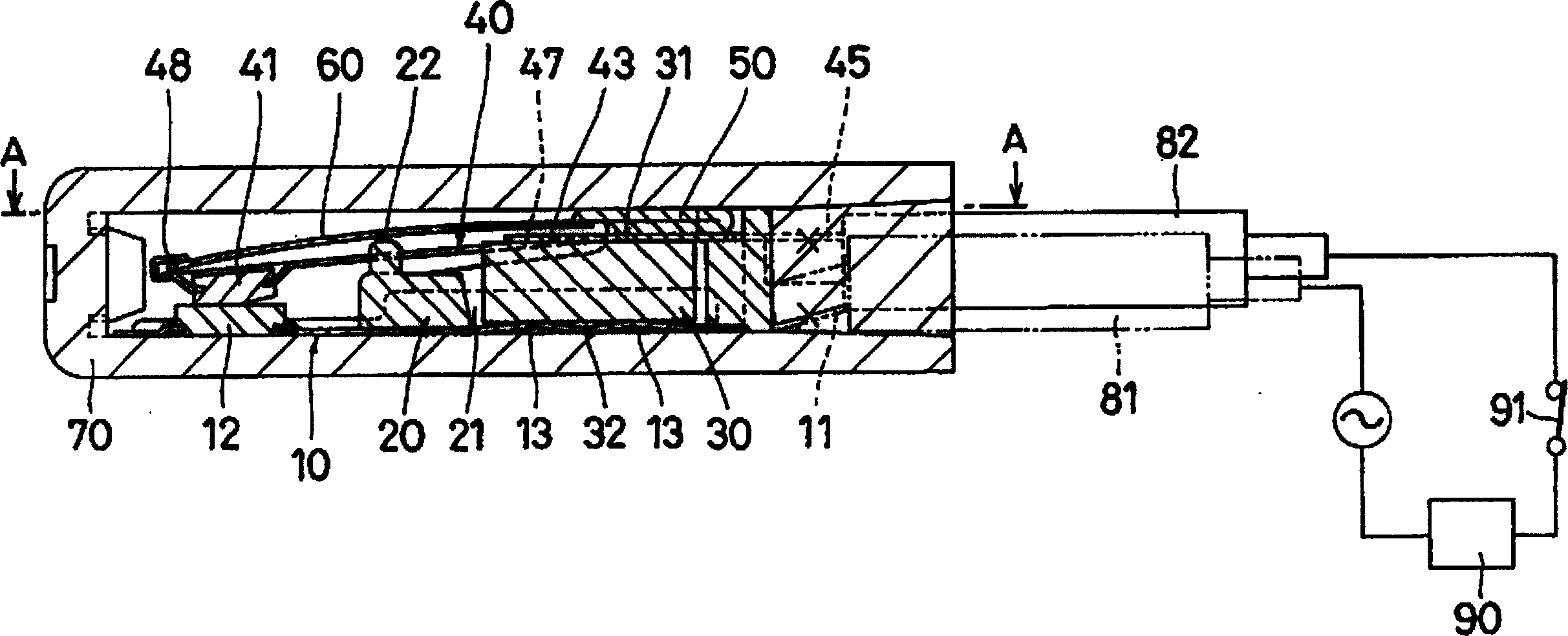
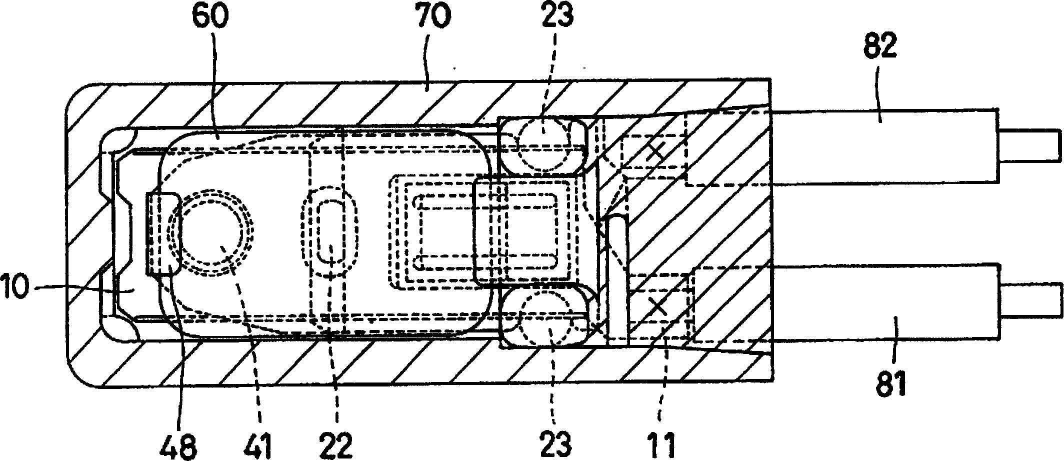
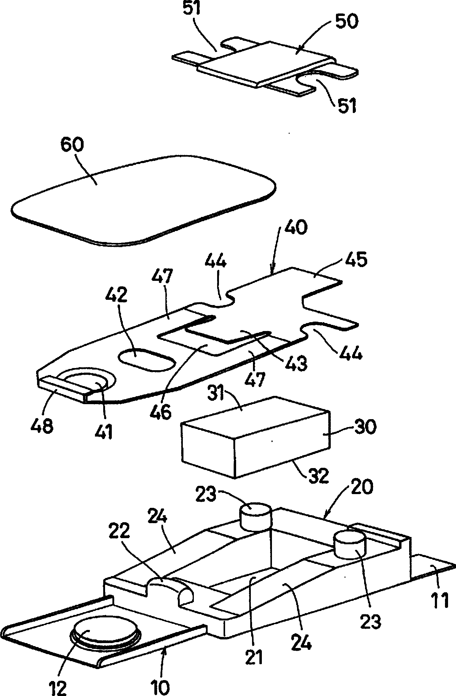
[0040] figure 1 is a longitudinal sectional view of a thermal protector structure according to the present invention, figure 2 yes figure 1 Sectional view taken along A-A, image 3 is a cross-sectional view of a thermal protector according to the present invention.

[0041] In these figures, a fixed plate 10 made of an elastic metal plate is formed with a terminal 11 for connection to the outside at its rear end, and a fixed contact 12 is arranged at its front end.

[0042] On the fixed plate 10, a support block 20 formed of an electrically insulating resin material is fixedly provided. The support block 20 is formed with a square hole 21 through its central portion, which accommodates a rectangular heating resistor consisting of a PTC element, such as image 3 shown. In addition, the support block 20 is formed with a protrusion 22 at the center of the upper surface of the front end thereof, and posts 23 are formed at both sides of the upper surface of the rear end the...


PUM


Abstract

The central portion of a movable plate 40 is cut into a U shape to form a tongue 43 provided along the longitudinal axis of the movable plate 40, the tongue 43 is brought into close contact with an upper electrode face 31 of a heating resistor 30, a lower electrode face 32 of the heating resistor 30 is brought into contact with a fixed plate 10, and portions of the movable plate 40 located on both sides of a cut 46 operate as an elastic arm 47.

Description

technical field [0001] The present invention relates to a thermal protector incorporated in transformers, motors and the like. More particularly, it relates to a self-sustaining type thermal protector combined with a heating resistor composed of PTC (Positive Temperature Coefficient) to maintain an open state by heat generated by the heating resistor. Background technique [0002] There has hitherto been proposed a thermal protection resistor in which a PTC element such as a positive thermistor is added as a heating resistor to keep an open state by heat generated by the heating resistor. [0003] Figure 12 shows a thermal protector of the type proposed in Japanese Patent Application 7-282701. [0004] In this kind of thermal protector, the load current flows in this order or in the opposite order: terminal a for connecting with the outside→bimetal b→movable contact c→fixed contact d→fixed electrode e→ Terminal f for external connections. [0005] When the temperature of...

Claims


Application Information

Patent Timeline
IPC IPC(8): H01H37/32H01H1/50H01H37/54
CPCH01H2037/5481H01H1/504H01H37/5418
Inventor 武田秀昭
Owner UCHIYA THERMOSTAT
Learn More