
Electronic control device

An electronic control and electronic technology, applied in printed circuit manufacturing, electrical equipment shell/cabinet/drawer, printed circuit, etc., can solve the problems of enlarging the shell, unable to dissipate heat, and loading power components, etc., and achieve a small structural height , low price, compact structure

Inactive Publication Date: 2005-04-06
ROBERT BOSCH GMBH
View PDF0 Cites 0 Cited by
  • Summary
  • Abstract
  • Description
  • Claims
  • Application Information

AI Technical Summary

Problems solved by technology

[0003] A disadvantage of this known controller is that the installation of the power components in the housing is problematic since there is no heat sink and the heat cannot be dissipated from the closed plastic housing to the environment
In addition, it is inconvenient to fit the radiator into the case, and has the disadvantage of causing the case to enlarge
It is not possible to ideally dissipate heat while having a simple mechanical structure with this known controller

Method used


Image

  • Electronic control device
  • Electronic control device
  • Electronic control device

Examples


Embodiment Construction

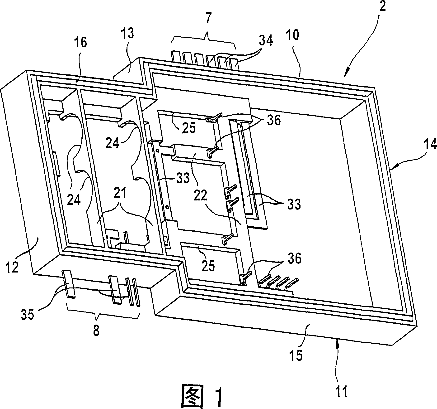
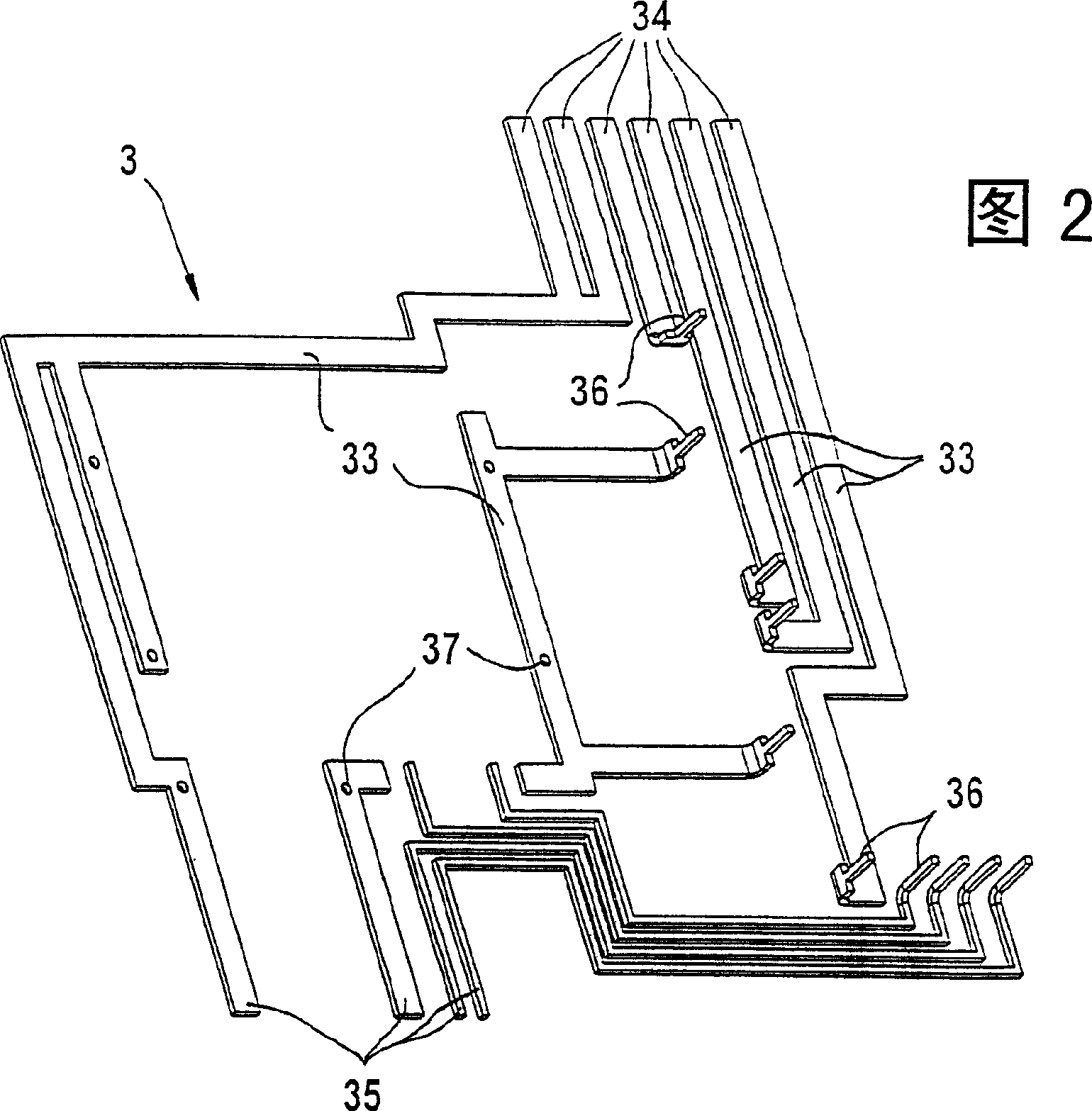
[0020] As shown in Figure 1, the housing 1 of the control instrument of the present invention comprises a housing frame 2 made of four side walls 12, 13, 14, 15, the housing frame 2 has an open lower side 11 and an open 10 on the upper side. The frame has a circumferential seal 16 on its top side 10 and bottom side 11 . Housing frame 2 is formed as an injection-molded part made of plastic and has metal conductor strips 33 partially embedded therein. The conductor strip 33 is formed by a punched grid 3, which is best seen in FIG. 2 . The conductor strips passing through the stamped grid 3 form the contact elements 34 for a first plug part 7 and the contact elements 35 for a second plug part 8 as well as conductor sets for conducting high currents. Some of the conductor strips 33 are provided with holes 37 for connection pins of electronic components. The ends of the conductor strips 33 are partially bent at right angles, wherein the bent ends form contact sections 36 for con...


PUM


Abstract

The invention relates to an electronic control device having a printed circuit board that is provided with electric and / or electronic components and is arranged in a closed housing and at least one connector component that is arranged on the housing. The contact elements of the connector component are at least partially embedded in the housing and are electrically connected to the printed circuit board. The aim of the invention is to obtain good heat dissipation of the heat that is produced by the power components, a construction that is as compact as possible and easy assembly. The housing comprises a housing frame which is embodied as an injection moulded part and has an open upper side and lower side. Metallic conductor bars which are produced by at least one pressed screen are partially embedded in said frame. The lower side of the housing frame is closed by means of a metallic bottom component acting as a heat sink and the upper side is closed by means of a lid component. The power components are arranged between the bottom component and the printed circuit board. The connections of the power components contact the printed circuit board and / or the conductor bar. The lower side of the power components is formed by a cooling plate, faces away from the printed circuit board and is connected to the bottom component in such a way that heat is conducted.

Description

technical field [0001] The invention relates to an electronic controller. Background technique [0002] Such a controller is known from DE 198 51 445 A1 and is used, for example, to control a drive unit driven by an electric motor. This known controller comprises a box-shaped base part made of plastic, provided with two plug elements, in which the printed circuit board is accommodated and can be closed with a cover. The box-shaped bottom part is produced together with the plug part as an injection-molded part. [0003] A disadvantage of this known control unit is that the installation of the power components in the housing is problematic since there is no heat sink and the heat cannot be dissipated from the closed plastic housing into the environment. In addition, it is inconvenient to fit the radiator into the case, and has the disadvantage of causing the case to be enlarged. With this known control unit, it is not possible to simultaneously have a simple mechanical stru...

Claims


Application Information

Patent Timeline
Patent Type & Authority Patents(China)
IPC IPC(8): B60R16/02B60R16/023H05K1/02H05K1/18H05K3/20H05K3/30H05K5/00H05K7/04H05K7/06H05K7/14H05K7/20
CPCH05K2201/09727H05K2201/0999B60R16/0239H05K1/0203H05K3/301H05K7/209H05K2201/10166H05K3/202H05K1/182H05K2201/10015H05K2201/09118H05K7/20
Inventor 京特·里尔伯恩哈德·塞福林
Owner ROBERT BOSCH GMBH
Learn More