
Method for manufacturing conductive plastic sheet

A plastic sheet material and manufacturing method technology, applied in the direction of heating methods, electrical components, electric heating systems, etc., can solve problems such as the difficulty of scaling up the use, the difficulty of adjusting the slit of the annular jaw gasket, etc., and achieve the manufacturing price and The effect of reducing construction costs

Inactive Publication Date: 2005-02-02
清川晋 +1
View PDF1 Cites 0 Cited by
  • Summary
  • Abstract
  • Description
  • Claims
  • Application Information

AI Technical Summary

Problems solved by technology

[0024] Conventional manufacturing devices also had problems in device fabrication and stable operation. For example, it was difficult to stably insert the electrodes arranged on both sides of the conductive plastic sheet.
[0025] In addition, when it is desired to slightly increase the thickness of the conductive plastic sheet at the part where the electrode wire is arranged, it is difficult to adjust the slit of the ring-shaped jaw spacer.
For these reasons, it is quite difficult to scale up and use the conventional segment-type device substantially intact.

Method used


Image

  • Method for manufacturing conductive plastic sheet
  • Method for manufacturing conductive plastic sheet
  • Method for manufacturing conductive plastic sheet

Examples


Embodiment Construction

[0053] Hereinafter, embodiments of the present invention will be described with reference to the drawings.

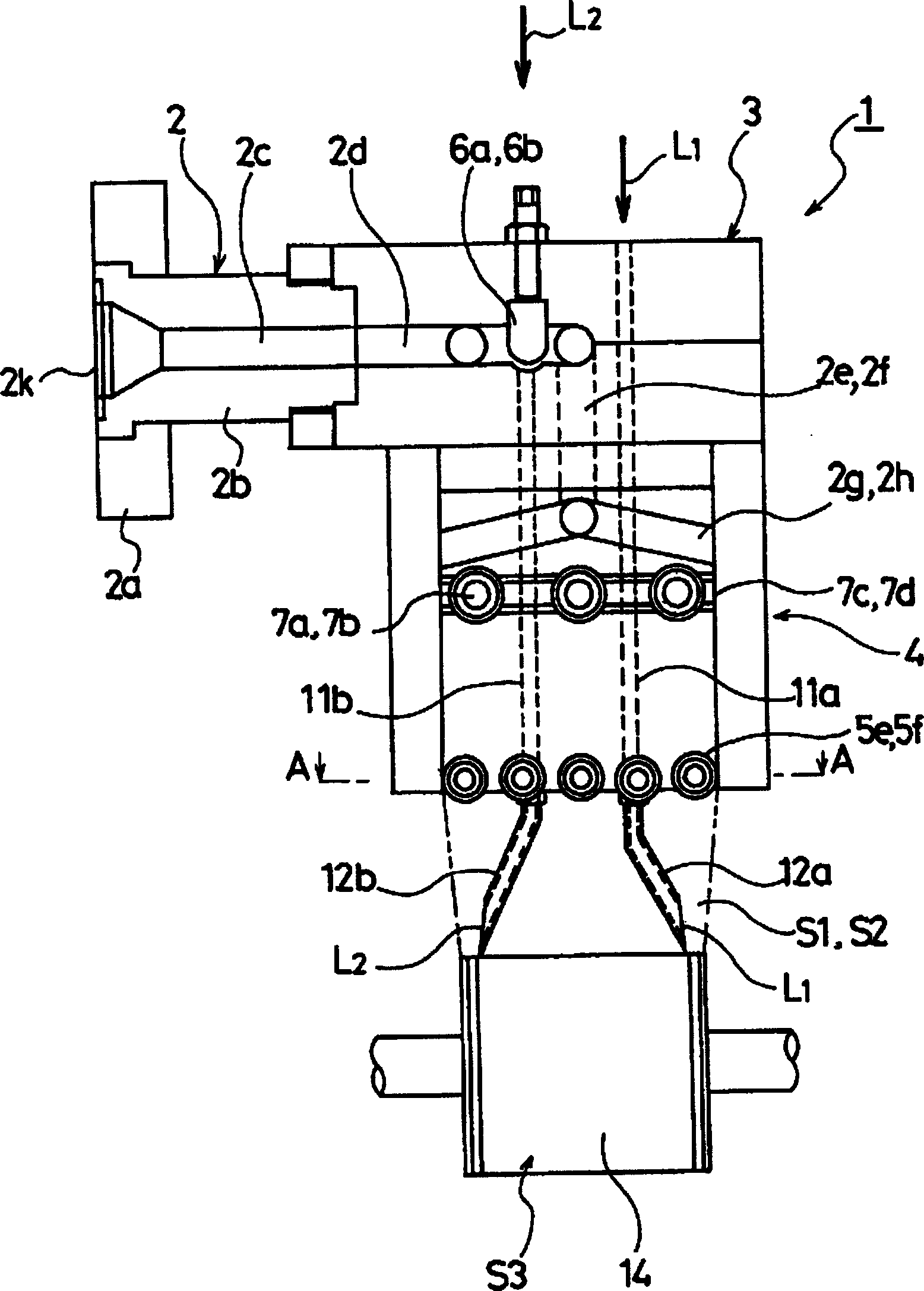
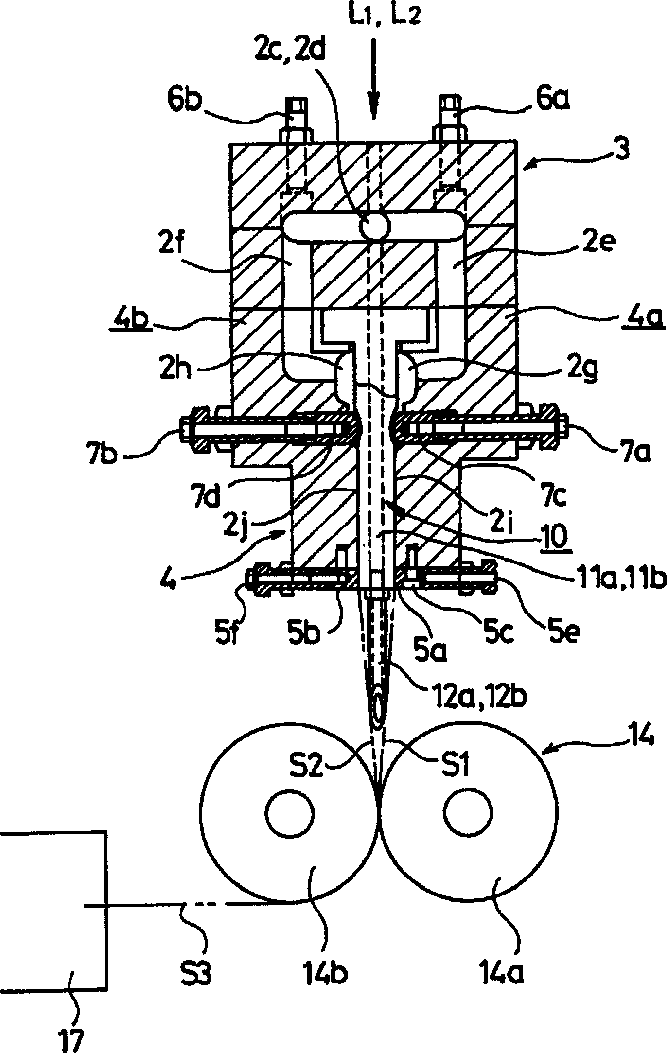
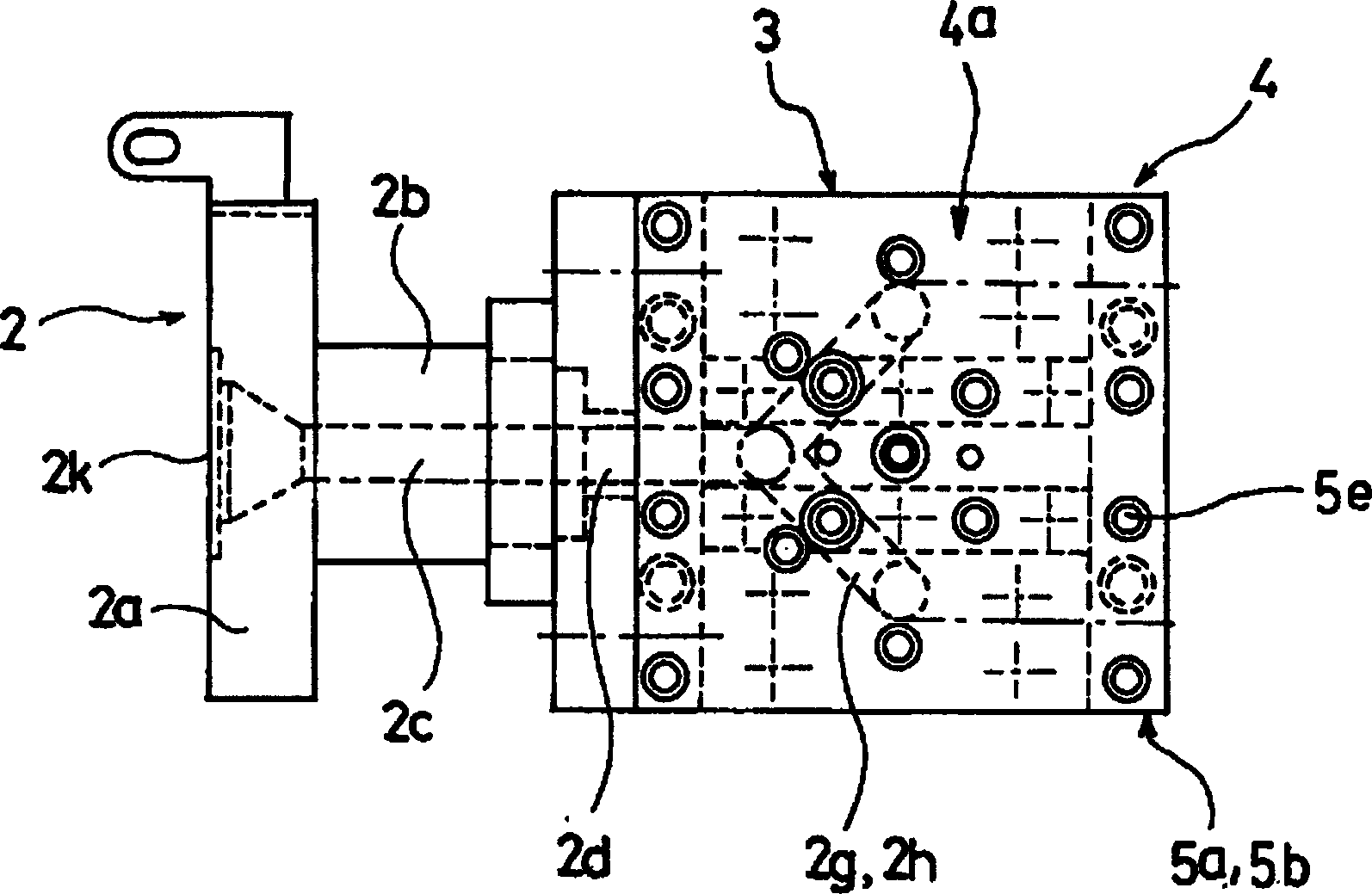
[0054] figure 1 It is a front sectional view of the forming apparatus of the conductive plastic sheet according to the embodiment of the present invention, figure 2 yes figure 1 A longitudinal section view of the device shown, image 3 is a plan view of the above forming device, Figure 4 is along figure 1 A cross-sectional view taken on line A-A in, Figure 5 6 is a schematic view showing the outline of the flow path of molten plastic in the metal mold, and FIG. 6 is a perspective view showing the outline of the entire molding device.

[0055] The forming device 1 of a conductive plastic sheet suitable for a planar heating element is composed of a metal mold device and an extrusion roller part 14. The former is a connection fitting 2 and a distribution fitting 3 connected to an extruder not shown in the figure. Composed of sheet material forming accessories 4; t...


PUM

PropertyMeasurementUnit
diameteraaaaaaaaaa
thicknessaaaaaaaaaa
lengthaaaaaaaaaa

Abstract

To provide a conductive plastic sheet wider than the conventional one. SOLUTION: The manufacturing method of the conductive plastic sheet is to melt conductive plastic, let it flow into two branched channels, extrude it in parallel from mouthpieces 5a, 5b with linear slits into two sheets S1 , S2 , and at same time, to arrange two electrode lines L1 , L2 near both ends and between the two formed sheets to deliver them together with the sheets, then, to pressure weld the two formed sheets into one integrated sheet L3 .

Description

technical field [0001] The invention relates to a conductive plastic sheet and its manufacturing method, which is suitable for sheet-like heating elements with a wide width, and is used in agricultural applications such as floor heating, seedling beds, pig raising, and chicken raising, or other uses. Used when heating a large area. Background technique [0002] For example, the widely used floor heating device is to lay a planar heating element on the wooden floor under the floor of the residential house or on the concrete floor surface, and then lay the floor on it by means of heat insulating material. [0003] Various planar heating elements are used in the above-mentioned floor heating devices, but when these devices are mainly classified, there are heat medium floor heating type and electric floor heating type. [0004] The heat medium floor heating type is laid on the crossbeam under the floor or on the concrete floor surface, and a groove with a zigzag heating structu...

Claims


Application Information

Patent Timeline
Patent Type & Authority Patents(China)
IPC IPC(8): H05B3/20B29C47/02B29C47/06B29C47/08B29C47/88B29C48/31B29C70/88B29K105/22B29L7/00B29L9/00F24D13/02H05B3/02H05B3/14
Inventor 清川晋清川太郎
Owner 清川晋
Learn More