
Guided servo direction control valve

A directional control valve, servo-driven technology, applied in the direction of servo motor components, fluid pressure actuating devices, mechanical equipment, etc., can solve the problems of complex system structure, high manufacturing cost, many leakage points, etc., to achieve simple system structure, reduce Additional energy consumption, low manufacturing cost effect

Inactive Publication Date: 2005-01-26
皮钧
View PDF0 Cites 0 Cited by
  • Summary
  • Abstract
  • Description
  • Claims
  • Application Information

AI Technical Summary

Problems solved by technology

[0003] The position of the main spool of the above-mentioned high pressure and large flow directional control valve is determined by the pressure difference of the control oil and the balance force of the balance spring, so the fluctuation of the control oil pressure, the accuracy of the spring stiffness change and the hydraulic force will all affect the positioning accuracy of the main spool and stability
Secondly, because there is a certain distance between the control port of the proportional pressure reducing valve and the oil passage connecting the control port of the left and right end covers of the main valve, the response speed of the main valve is relatively low.
In addition, since the main valve and the proportional pressure reducing valve are two separate components, the structure of the system is complicated, there are many leakage points, and the manufacturing cost is high.
At the same time, since the oil inlet port of the proportional pressure reducing valve is a normal pressure port, the additional energy consumption is relatively large

Method used


Image

  • Guided servo direction control valve
  • Guided servo direction control valve

Examples


Embodiment Construction

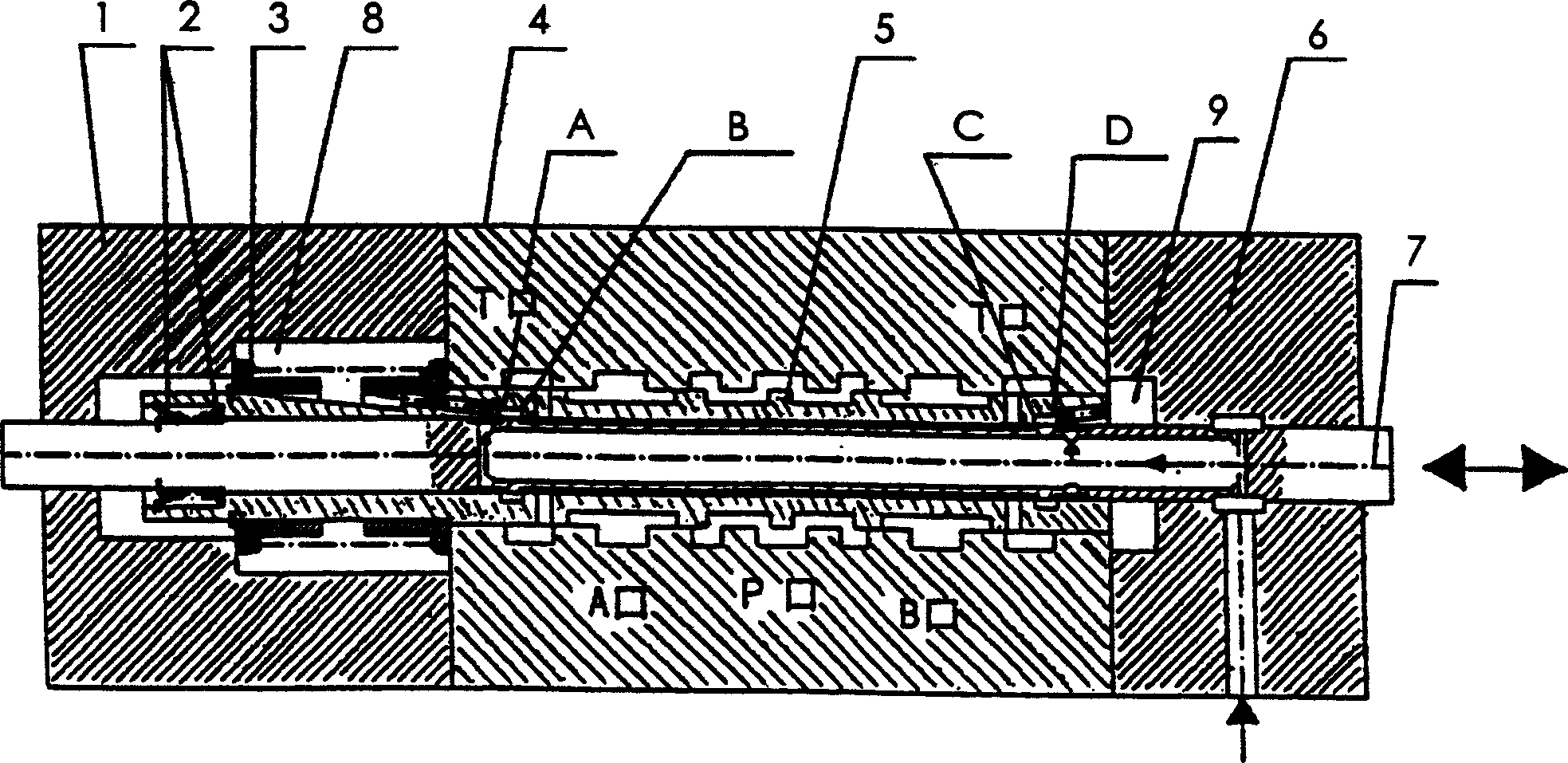
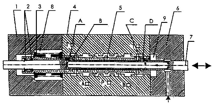
[0010] Such as figure 1 Shown, the present invention is made up of left end cover 1, control spool balance spring 2, main valve balance spring 3, main valve body 4, main spool 5, right end cover 6 and control spool 7. The left end cover 1 is connected and fixed on the main valve body 4 , and is sealed with the main valve body 4 to form a left control chamber 8 . There is a circular hole coaxial with the circular hole of the main valve body and with a diameter equal to the diameter of the control valve core 7 on the side, and determines the neutral position of the main valve. The right end cover 6 is connected and fixed on the valve body, and is sealed with the valve body 4 to form a right control chamber 9 . There is a round hole coaxial with the round hole of the main valve body and the diameter is equal to the diameter of the control valve core 7 on the side, and an annular groove with a certain width is arranged on the round hole, and an oil port is connected to the contro...


PUM


Abstract

A control valve of driving direction for guide servo consists of left end cover and right end cover, balance spring for control valve core, balance spring for main valve, main valve body, main valve core and control valve core. The left and right end covers will be fixed on the main valve body to form left and right control cavities together with the main valve body and there will be ring slot of oil channel, circular hole and oil channel connecting through to external in the main valve body. The control valve core will be set in the hole of main valve core as its two sleeves for raising shoulders to be corresponded to two circular ring slots on the main valve i.e symmetrical centre line for width of the circular ring slot to be coincided with symmetrical centre line for width of the sleeve for raising shoulder.

Description

(1) Technical field [0001] The present invention relates to a valve, in particular a pilot servo driven directional control valve. (2) Background technology [0002] At present, for high pressure and large flow (above 32 diameter) directional control valves, some large hydraulic parts production companies such as German Rexroth (REXROTH), American Parker (PARKER), Japan Yuken (YUKEN) and some domestic hydraulic pressure Parts production company (see 1. "Construction Machinery Hydraulic Products", American Parker Company Sample HY02-8029 / C, January 2002; 2. "Walking Machinery Hydraulic Components", German REXROTH Company Hydraulic Product Manual, Volume XI; 3 , "Yuken Hydraulic Products", Japanese YUKEN Company's 1995 Chinese version engineering information catalog; 4, "Multi-way reversing valve and other valves" sample, Changjiang Hydraulic Parts Factory) in order to overcome the large operating force and realize proportional control and remote control and other difficultie...

Claims


Application Information

Patent Timeline
Patent Type & Authority Patents(China)
IPC IPC(8): F15B13/02
Inventor 皮钧
Owner 皮钧
Learn More