Photoelectric device and producing method thereof

An electro-optic device and electro-optic technology, applied in identification devices, optics, nonlinear optics, etc., can solve problems such as effective voltage drop, display contrast drop, and easy degradation of metal films

Inactive Publication Date: 2005-01-12
SEIKO EPSON CORP
View PDF0 Cites 0 Cited by
  • Summary
  • Abstract
  • Description
  • Claims
  • Application Information

AI Technical Summary

Problems solved by technology

[0005] However, in the liquid crystal display device having such a structure, since the voltage applied to the liquid crystal 50 between the transparent electrode 132 and the reflection plate 109 through the transparent electrode 108 drops at the reflection plate 109, the effective voltage also drops, and therefore, Display Contrast Decreased
Also, since the reflection plate 109 is exposed in a bare state on the side opposite to the liquid crystal, the metal film used to form the reflection plate 109 tends to degrade

Method used


Image

  • Photoelectric device and producing method thereof
  • Photoelectric device and producing method thereof
  • Photoelectric device and producing method thereof

Examples


Embodiment Construction

[0113] The electro-optical device and its manufacturing method according to the embodiments of the present invention will be specifically described below with reference to the accompanying drawings.

[0114] (Basic structure of an electro-optic device)

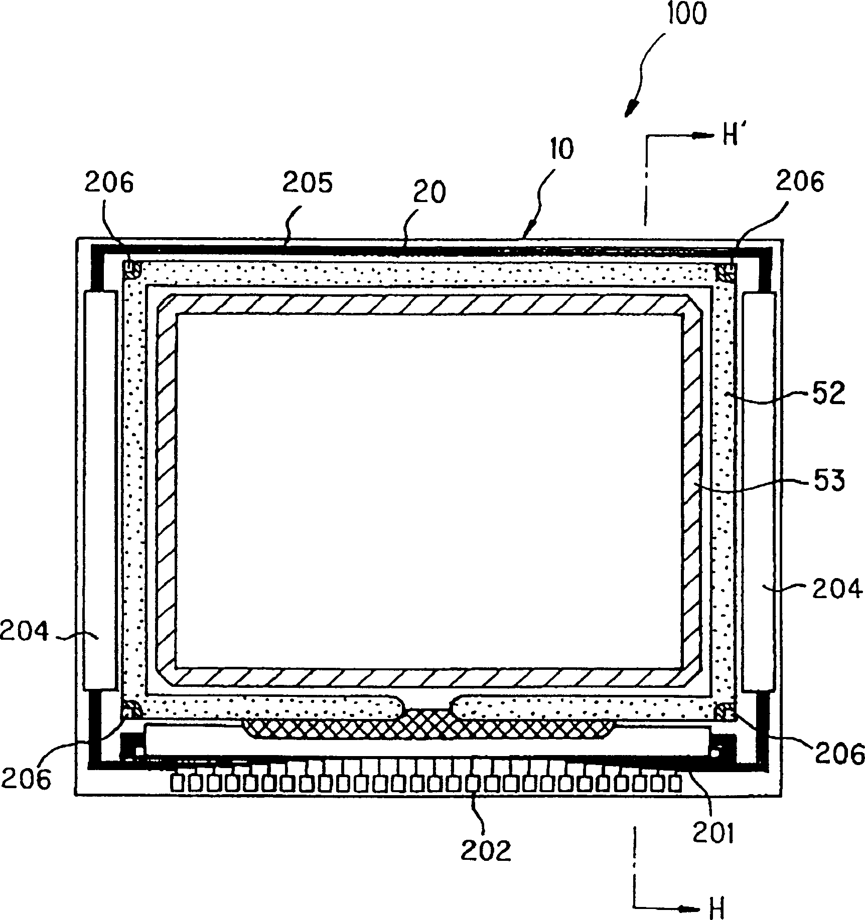
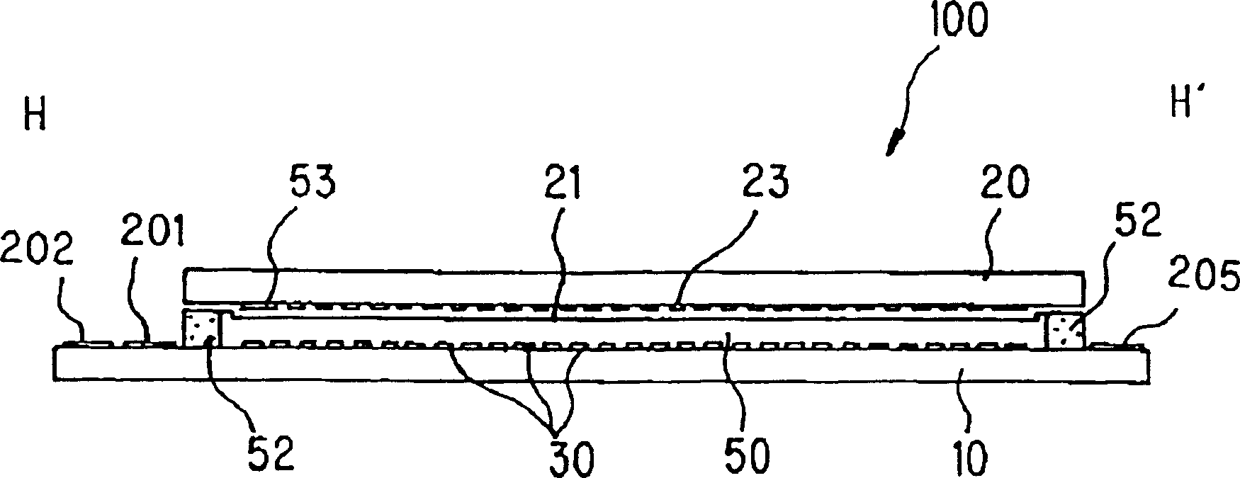
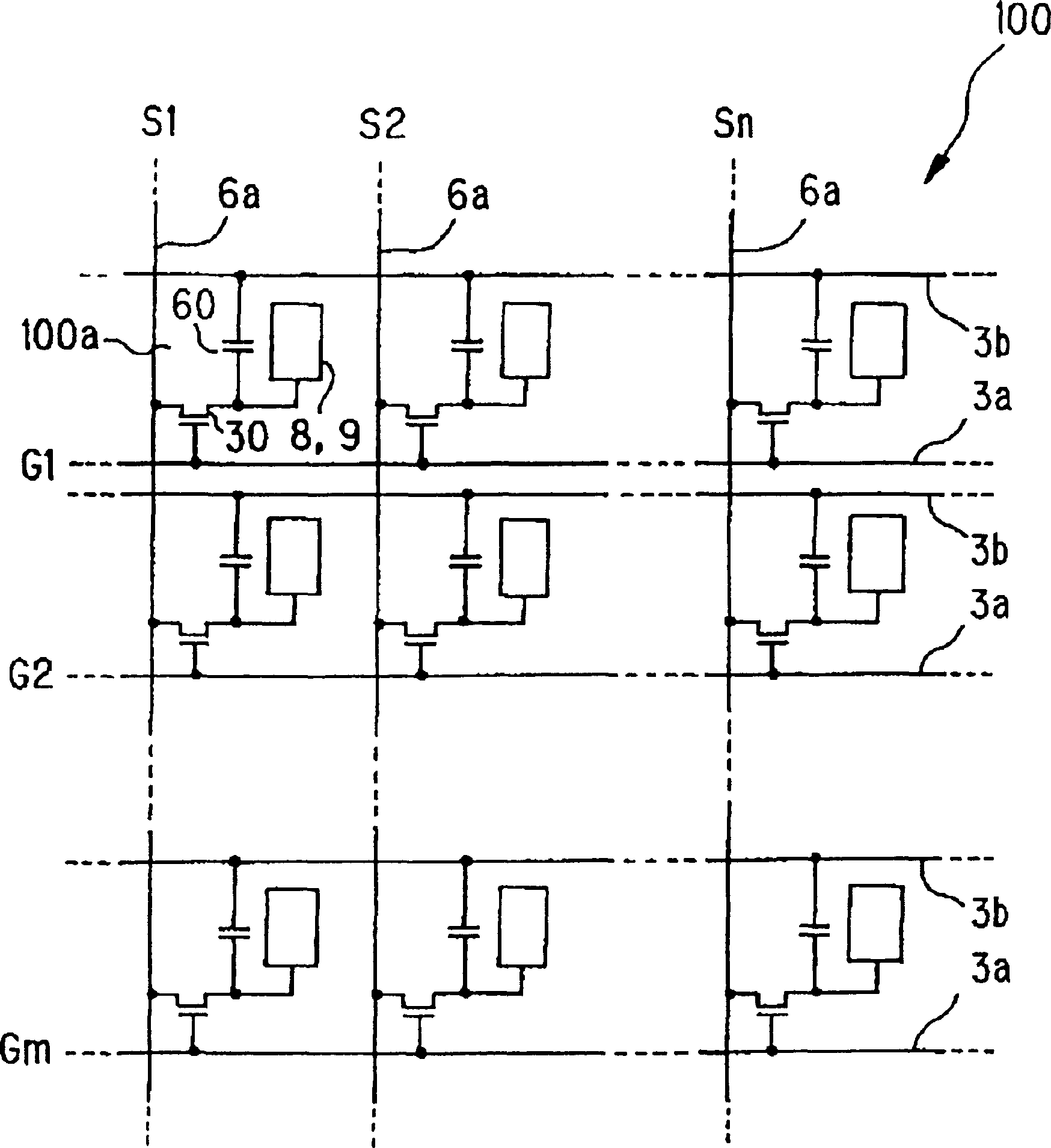
[0115] figure 1 is a plan view of a liquid crystal display device with various constituent parts as an electro-optical device according to an embodiment of the present invention, which is viewed from the side of the counter substrate, figure 2 is along figure 1 The cross-sectional view of the line H-H' in the middle. image 3 It is an equivalent circuit diagram of elements, wires, etc. of a plurality of pixels formed in a matrix in an image display region of an electro-optic device (liquid crystal display device). In the drawings used to describe the present embodiment, layers and components are shown in different scales so that they can be seen in the drawings.

[0116] exist figure 1 and figure 2 In the electro-op...


PUM

PropertyMeasurementUnit
thicknessaaaaaaaaaa
thicknessaaaaaaaaaa
thicknessaaaaaaaaaa

Abstract

The invention provides an electrooptic device which is suitable for use in a portable telephone, a mobile computer, and the like, and in which the effective voltage to be applied to the liquid crystal is high, high-contrast display is possible, and a reflective electrode is prevented from deteriorating. The invention also provides a production method for the electrooptic device. An electrooptic device includes a pair of substrates opposing each other so as to seal and hold liquid crystal therebetween, and a reflective plate that is formed on the side of one of the substrates close to the liquid crystal and that has one or more openings, each at a predetermined position, to reflect incident light from the other substrate and to transmit light from a backlight source. A transparent electrode is formed on the reflective plate, and is electrically connected to a drain electrode or a semiconductor layer.

Description

technical field [0001] The invention relates to an electro-optical device and a manufacturing method thereof. In particular, it relates to an electro-optic device suitable for use in portable computers, mobile phones, etc. and its manufacturing method, wherein the effective voltage applied to liquid crystal is very high, high display contrast can be obtained, and degradation of reflective electrodes and reflective plates can be avoided. Background technique [0002] Electro-optical devices such as liquid crystal display devices and EL light-emitting display devices are widely used as direct-view display devices in electronic devices such as portable computers and mobile phones. For example, in the active matrix type transflective liquid crystal display device of this electro-optic device, the TFT array substrate and the counter substrate facing each other are bonded together with a sealing material, and the liquid crystal serving as the electro-optical substance is sealed an...

Claims


Application Information

Patent Timeline
Patent Type & Authority Patents(China)
IPC IPC(8): G02F1/136G02F1/1335G02F1/1343G02F1/1362G02F1/1368G09F9/00G09F9/30G09F9/35
CPCG02F2201/12G02F1/1362G02F2203/09G02F1/133553G02F1/133555G02F1/13439G02F1/136
Inventor 吉田俊明
Owner SEIKO EPSON CORP
Why Eureka
Try Eureka