Battery

A battery and battery shell technology, applied in the direction of circuits, battery pack parts, electrical components, etc., can solve the problems of hindering resin flow, battery economic loss, difficult to decompose and reuse, etc., to improve product manufacturing yield and high filling efficiency , to prevent unsightly effects

Inactive Publication Date: 2004-12-29
KYOCERA CORP
View PDF0 Cites 0 Cited by
  • Summary
  • Abstract
  • Description
  • Claims
  • Application Information

AI Technical Summary

Problems solved by technology

[0008] However, in the above-mentioned battery, the thickness dimension T1 of the battery case 1 and the short-side dimension T2 of the substrate main body 6 are set to be approximately the same. The width dimension T3 of the part 2 is set to be approximately the same as the thickness dimension T1 of the battery case 1, so when the molded part 2 is formed, the substrate main body 6 hinders the flow of the resin, and the filling efficiency of the resin is not high. Figure 4 As shown, the side surface of the substrate main body 6 is exposed on the surface of the molded part 2 after molding.
[0009] If the substrate main body 6 is exposed in the molding part 2, the battery cannot be marketed as a commercial product due to its unsightly appearance, and at the same time, it is difficult to disassemble and reuse, so from the viewpoint of cost balance, there is a great economic loss in battery manufacturing.

Method used


Image

  • Battery
  • Battery
  • Battery

Examples


Embodiment Construction

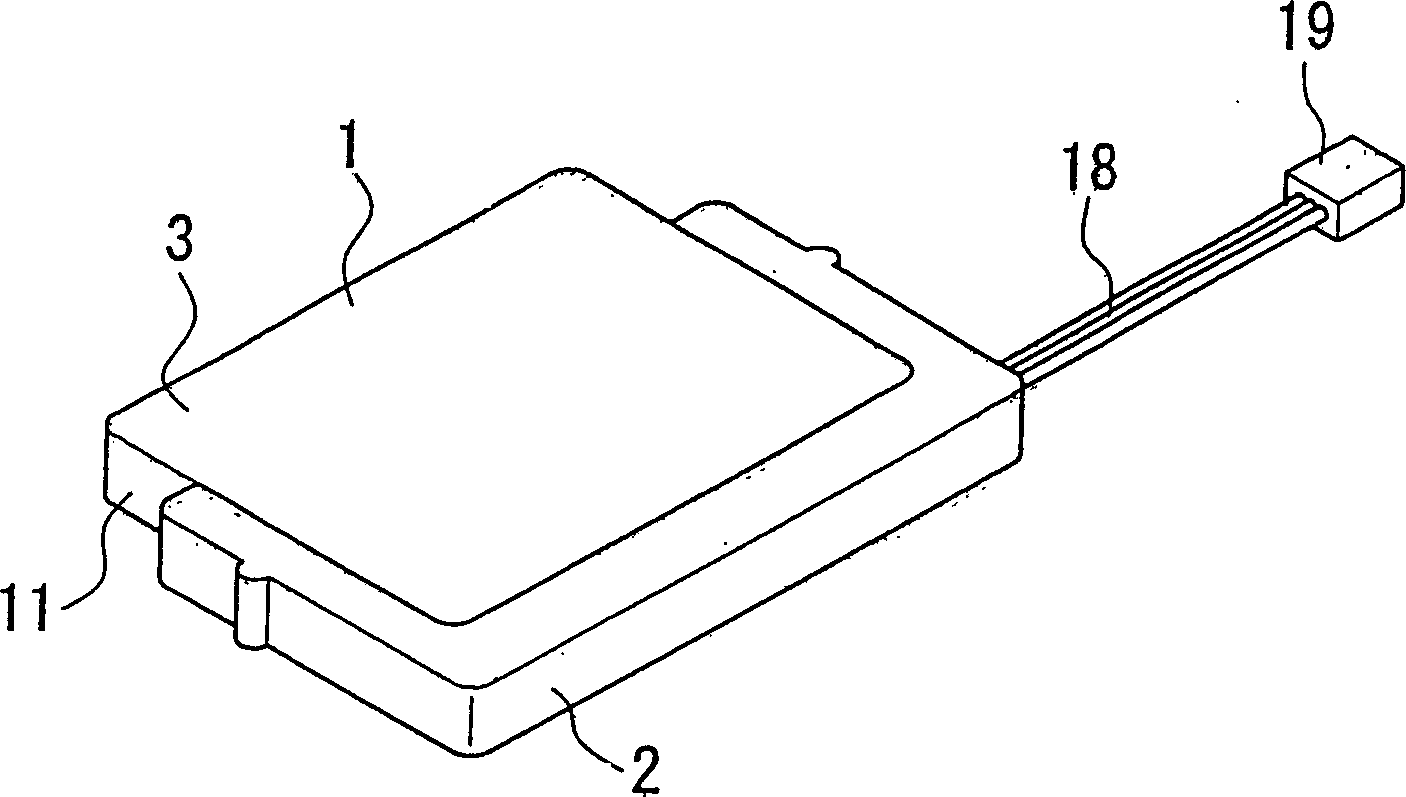
[0026] Hereinafter, an embodiment of the present invention will be described with reference to the drawings. figure 1 , figure 2 In the case where the present invention is applied to a battery for a portable terminal, the battery A for a portable terminal shown in these figures has a battery case 1 and a circuit board 5 disposed along the side surface 4 of the battery case 1, and the circuit board 5 is constituted by The molding part 2 is fixed on the battery case 1, and its basic structure is the same as that of the above-mentioned Figure 4 , Figure 5 Same as shown.

[0027] In addition, in Figure 1 ~ Figure 3 in, right with Figure 4 , Figure 5 The parts shown with the same structure are attached with the same reference numerals and will not be described. Below, only the Figure 4 , Figure 5 different parts.

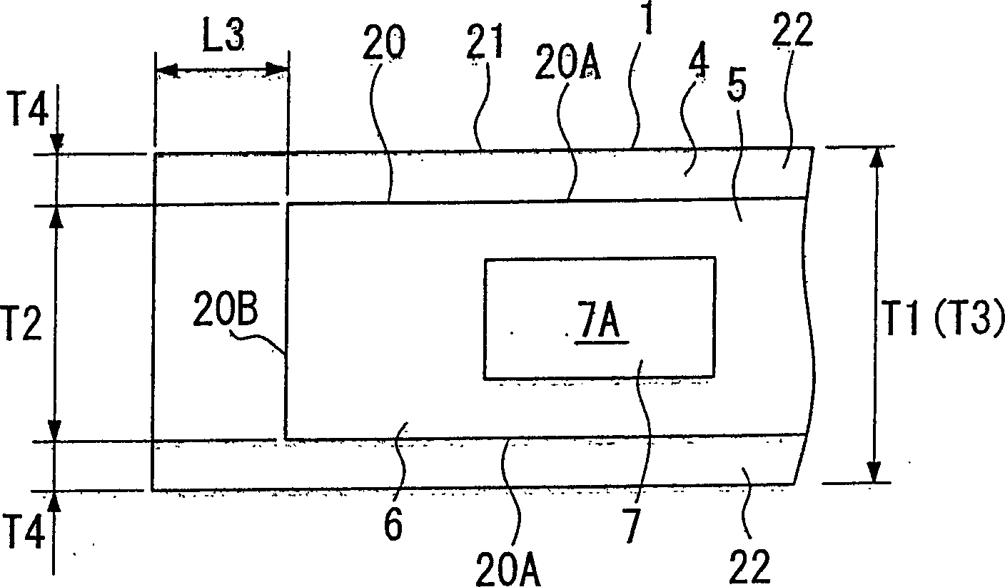
[0028] Portable terminal battery A with Figure 4 , Figure 5 The difference in structure is the size relationship between the circuit board 5 and the si...


PUM


Abstract

PROBLEM TO BE SOLVED: To provide a battery with a circuit board disposed along a battery cell and integrally fixed to the battery cell with a mold, having the improved filling efficiency of a resin in the mold, and allowing prevention of an appearance defect. SOLUTION: This battery A has a battery cell 1, and a circuit board 5 disposed along one face 4 of the battery cell 1, while the circuit board 5 is integrally fixed to the battery cell 1 with the mold 2. The circuit board 5 is formed such that at least border lines 20A each showing a border line in the width direction of a border line 20 when projecting the circuit board 5 upon the face 4 are positioned inside a border lien 21 of the face 4, and the circuit board 5 is embedded in the mold 2.

Description

field of invention [0001] The present invention relates to a battery used in portable terminals, and more particularly, to a battery having a structure in which a circuit board is integrally fastened to a battery case by a molded portion. Background technique [0002] Conventionally, as batteries used in portable terminals such as mobile phones, batteries having various circuit boards in a battery case, for example, a circuit board for protection against overcurrent, etc., have been provided. In general, this type of battery is integrally fastened with the battery case by using molding resin to fasten the above-mentioned circuit board from the viewpoint of ease of use and pattern design. [0003] Figure 4 , Figure 5 It is a figure which shows an example of the said conventional battery, Figure 4 Among them, the reference numeral 1 is the battery case, and the reference numeral 2 is the molding part. The battery case 1 is formed in a rectangular shape with a certain thic...

Claims


Application Information

Patent Timeline
Patent Type & Authority Patents(China)
IPC IPC(8): H01M2/20H01M2/00H01M2/10H01M2/30H01M2/34
CPCY02E60/12Y02E60/10
Inventor 山崎真人
Owner KYOCERA CORP
Why Eureka
Try Eureka