Phase-locked loop circuit capable of reducing phase deviation and not increasing operating voltage
A phase-locked loop and circuit technology, applied in the direction of electrical components, automatic power control, etc., can solve problems such as insufficient, achieve the effect of reducing phase offset and avoiding phase offset
- Summary
- Abstract
- Description
- Claims
- Application Information
AI Technical Summary
Problems solved by technology
Method used
Image
Examples
Embodiment Construction
[0066] Embodiments of the present invention will be specifically described below with reference to the accompanying drawings.
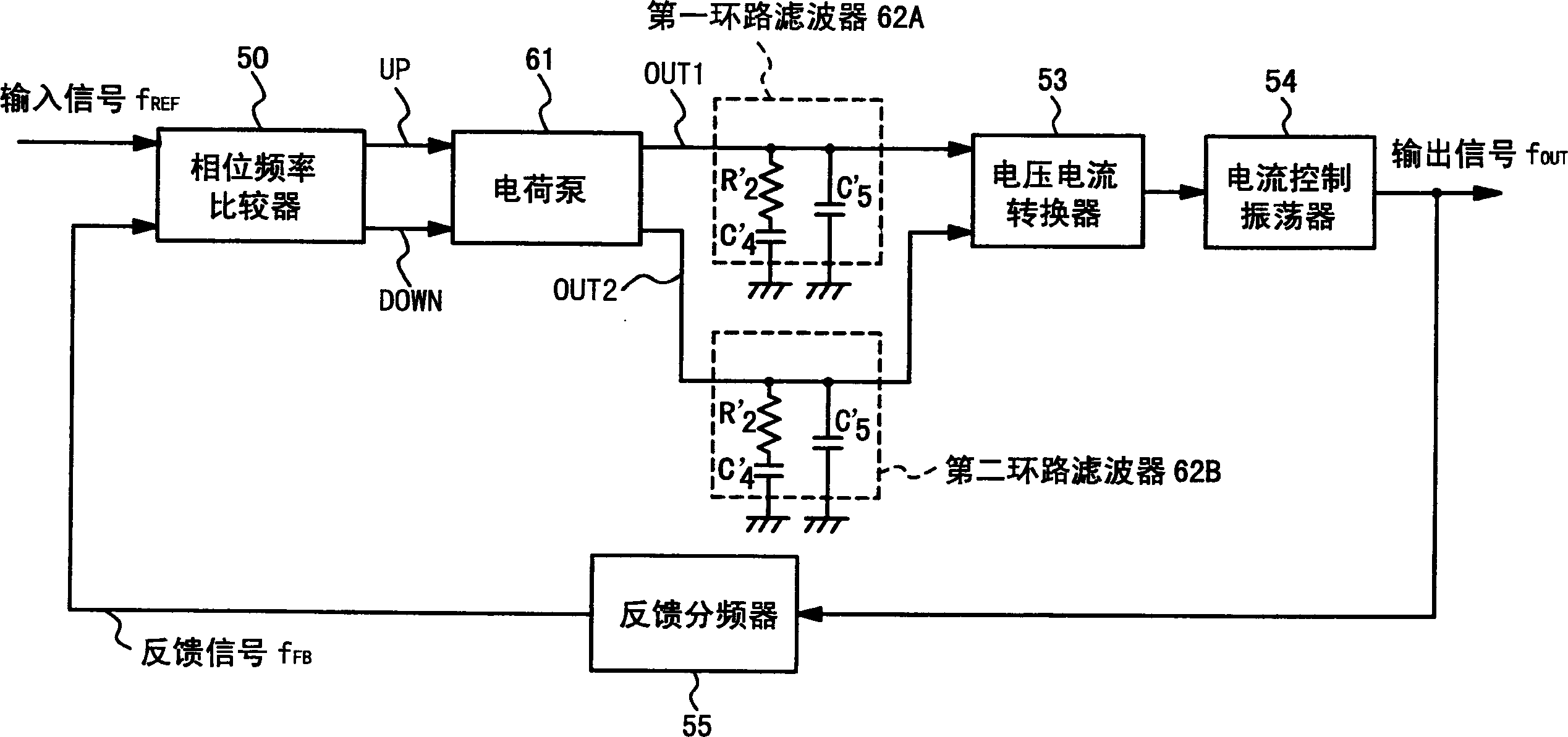
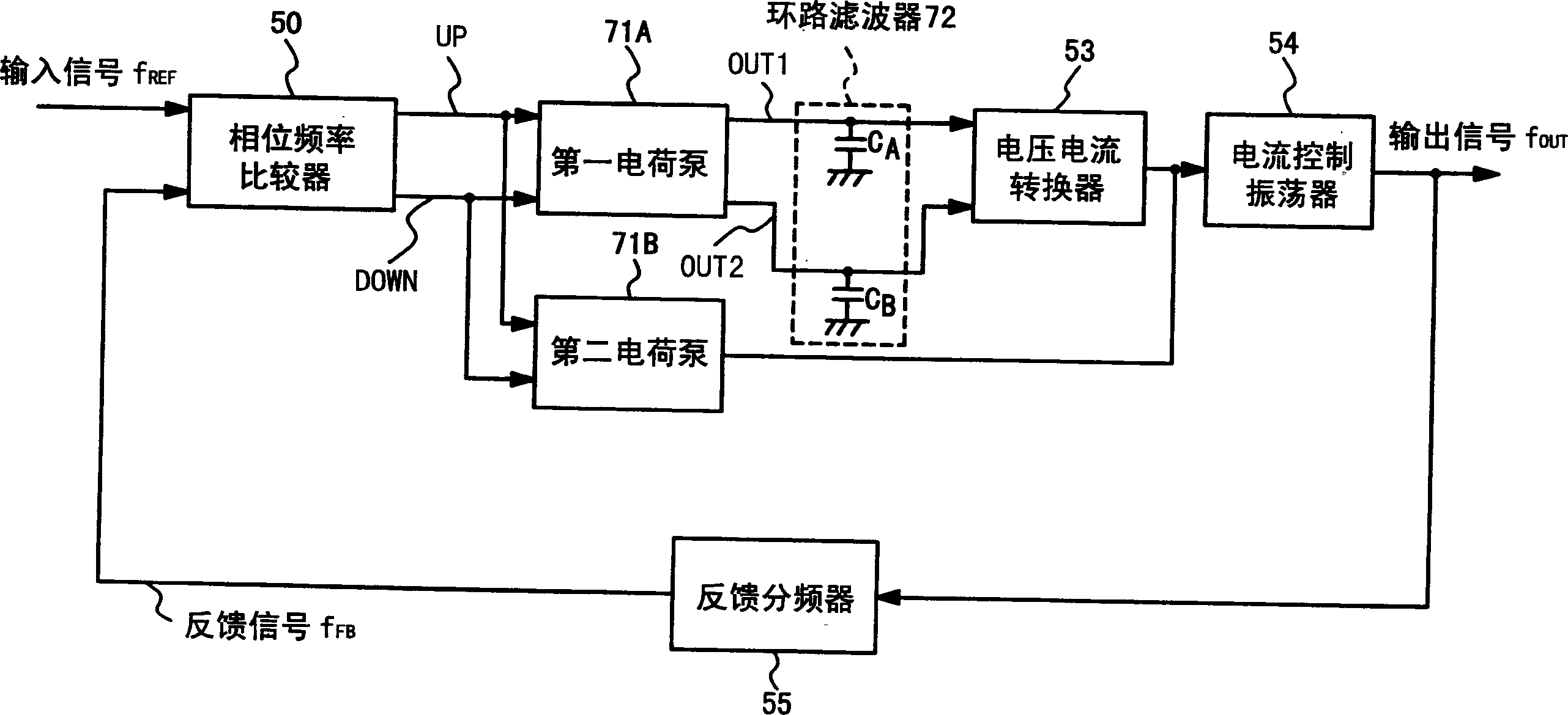
[0067] Figure 5 It is a block diagram showing the structure of a phase-locked loop circuit according to an embodiment of the present invention. This phase locked loop circuit has a phase frequency comparator 10 , an integrator 20 , a phase controller 21 , a current controlled oscillator 14 , a CTS buffer 15 and a feedback frequency divider 16 .
[0068] The phase-frequency comparator 10 takes the input signal f REF The phase and frequency are respectively related to the feedback signal F from the feedback frequency divider 16 FB The phase and frequency of the signal are compared to generate an increase signal UP and a decrease signal DOWN, both of which indicate the error of the signal. For example, a clock signal from an oscillator (not shown) is used as the input signal f REF . The increase signal UP generated by the phase-frequency comparator...
PUM
 Abstract
Description
Claims
Application Information
 - R&D Engineer
- R&D Manager
- IP Professional
- Industry Leading Data Capabilities
- Powerful AI technology
- Patent DNA Extraction
Browse by: Latest US Patents, China's latest patents, Technical Efficacy Thesaurus, Application Domain, Technology Topic, Popular Technical Reports.
© 2024 PatSnap. All rights reserved.Legal|Privacy policy|Modern Slavery Act Transparency Statement|Sitemap|About US| Contact US: help@patsnap.com


