Electromagnetic transducer and portable communication device
A transducer and electromagnetic technology, applied in the fields of electro-acoustic transducers and portable communication devices, can solve the problems of reduced driving force, inability to achieve sound pressure level, etc., and achieve the effect of reducing mass and strong magnetic gap value
- Summary
- Abstract
- Description
- Claims
- Application Information
AI Technical Summary
Problems solved by technology
Method used
Image

Examples
example 1
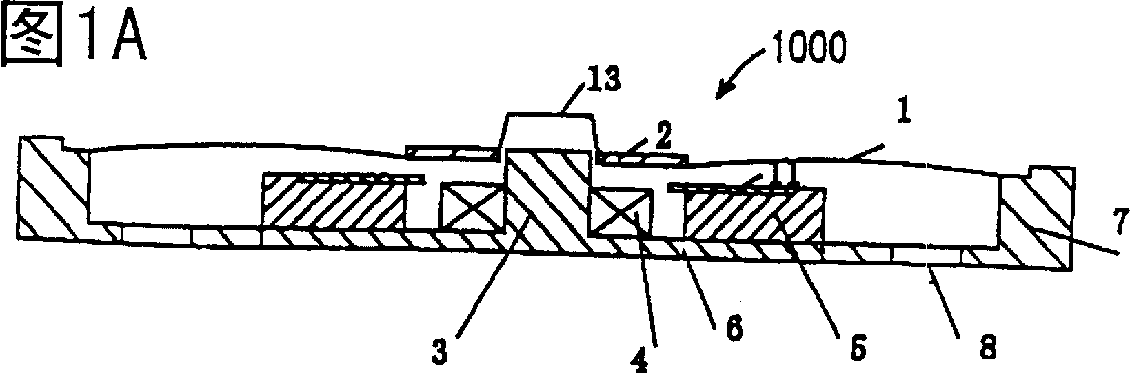
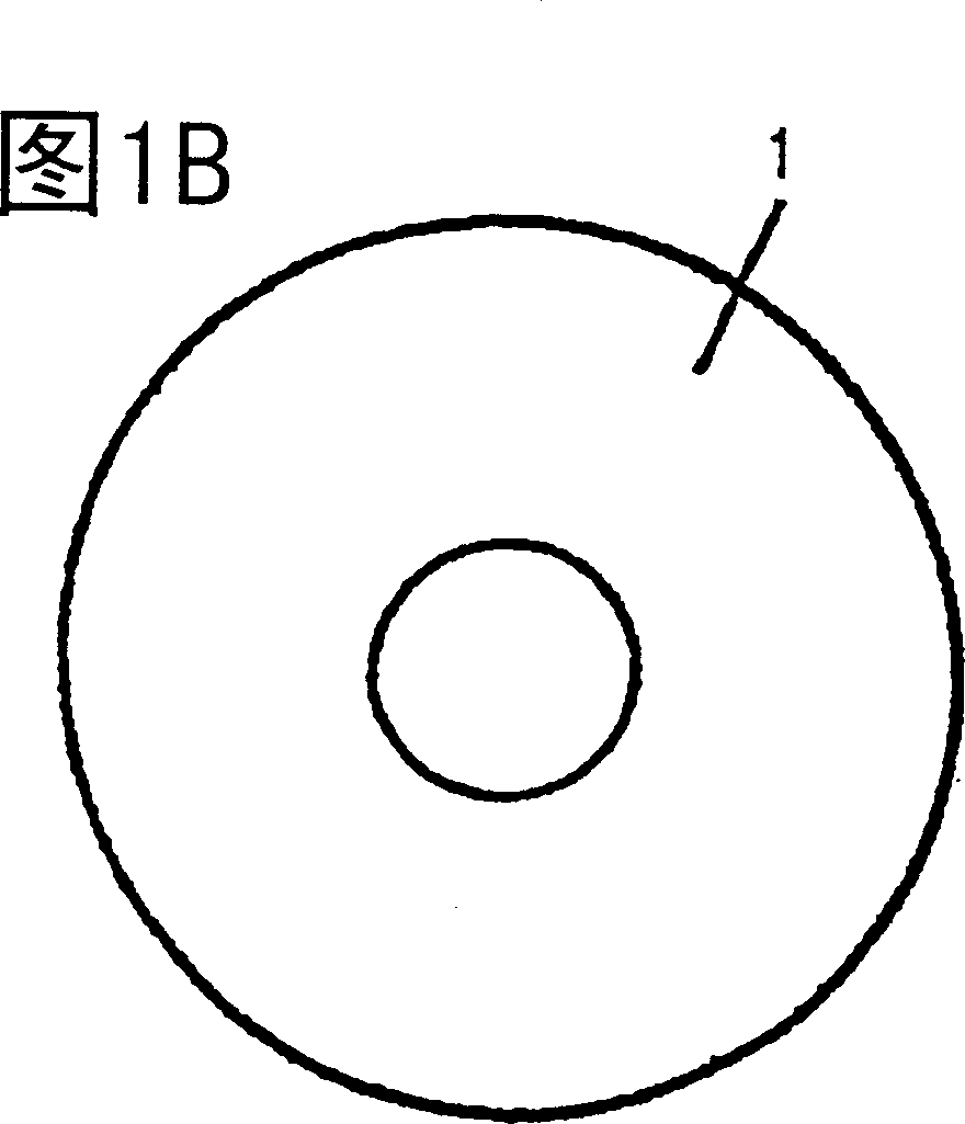
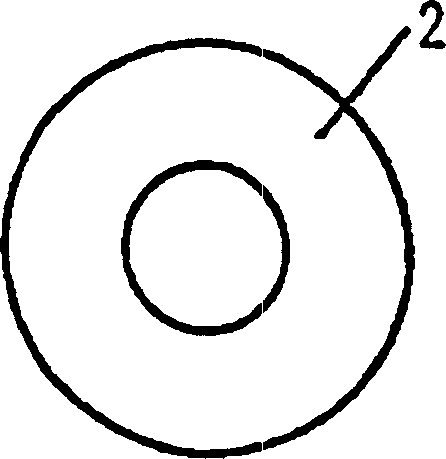
[0056] An electromagnetic transducer 1000 according to Example 1 of the present invention will be described below with reference to FIGS. 1A , 1B, 1C, 1D and 2 .
[0057] FIG. 1A is a cross-sectional view of an electromagnetic transducer 1000 according to Example 1 of the present invention. figure 2 is the magnetic flux vector diagram of the electromagnetic transducer 1000 according to Example 1 of the present invention. figure 2 The magnetic flux vector diagram of FIG. 2 shows only half of the electromagnetic transducer 1000 relative to the central axis (shown on the left side of the figure).
[0058] As shown in Fig. 1A, according to the electromagnetic transducer 1000 of the example 1 of the present invention, comprise a cylindrical first housing 7 and a yoke 6 (which is arranged to cover the lower surface of the first housing 7 disk-shaped). At the center portion of the yoke 6 is provided a center pole 3 which may constitute a part of the yoke 6 . Coil 4 surrounds cen...
example 2
[0072] An electromagnetic transducer 2000 according to Example 2 of the present invention will be described below with reference to FIGS. 4A , 4B and 5 .
[0073] 4A and 5 are respectively a cross-sectional view and a magnetic flux vector diagram of an electromagnetic transducer 2000 according to Example 2 of the present invention. Figure 5 The magnetic flux vector diagram of FIG. 1 shows only half of the electromagnetic transducer 2000 relative to the central axis (shown on the left side of the figure).
[0074] According to the electromagnetic transducer 2000 shown in FIG. 4A, a ring-shaped second magnet 9 as shown in the plan view of FIG. 4B is arranged above the second diaphragm 2 with a magnetic gap therebetween. The second magnet 9 is supported by a second housing 10 . A plurality of holes 12 for transmitting sound generated by the first and second diaphragms 1 and 2 and the cover 13 to an external space outside the second case 10 are provided in the second case 10 . ...
example 3
[0091] An electromagnetic transducer 3000 according to Example 3 of the present invention will be described below with reference to FIGS. 8A , 8B and 9 .
[0092] 8A and 9 are respectively a cross-sectional view and a magnetic flux vector diagram of an electromagnetic transducer 3000 according to Example 3 of the present invention. The flux vector diagram of FIG. 9 shows only half of the electromagnetic transducer 3000 relative to the central axis (shown on the left side of the figure).
[0093] The electromagnetic transducer 3000 shown in Fig. 8A comprises a second diaphragm 22 having an L-shaped cross-section at its inner periphery, one is arranged above the second diaphragm 22, and there is a second diaphragm 22 therebetween. magnetic gap of the ring-shaped second magnet 29, and a such as Figure 8B The annular second thin magnetic plate 24 is shown in plan view.
[0094] The second magnet 29 is supported by a second housing 20 . The second case 10 has a concave portion ...
PUM
 Abstract
Description
Claims
Application Information
 - Generate Ideas
- Intellectual Property
- Life Sciences
- Materials
- Tech Scout
- Unparalleled Data Quality
- Higher Quality Content
- 60% Fewer Hallucinations
Browse by: Latest US Patents, China's latest patents, Technical Efficacy Thesaurus, Application Domain, Technology Topic, Popular Technical Reports.
© 2025 PatSnap. All rights reserved.Legal|Privacy policy|Modern Slavery Act Transparency Statement|Sitemap|About US| Contact US: help@patsnap.com