


Quick Research
Generate reliable direction feasibility study reports for your R&D in just a few steps.

Technical Q&A
Discover and master advanced knowledge NOW. Basics, ideas, possibilities, all at once.

Find Solutions
As an expert in R&D theories, this can generate solutions to your technical problems instantly.

Evaluate Feasibility
Analyze your overall solution with one click, know your potential R&D risks in advance.

Monitor Landscape
Get weekly tech updates, stay abreast of the latest tech innovations and key insights.
Piezoelectric element
A technology for piezoelectric components and piezoelectric elements, applied in electrical components, piezoelectric/electrostrictive/magnetostrictive devices, circuits, etc., can solve the problem of increasing the number of manufacturing steps of piezoelectric components and increasing the manufacturing cost of piezoelectric components And other issues
- Summary
- Abstract
- Description
- Claims
- Application Information
AI Technical Summary
Problems solved by technology
Method used
Image

Examples
no. 1 example
[0019] (A first embodiment, Figures 1 to 5 )
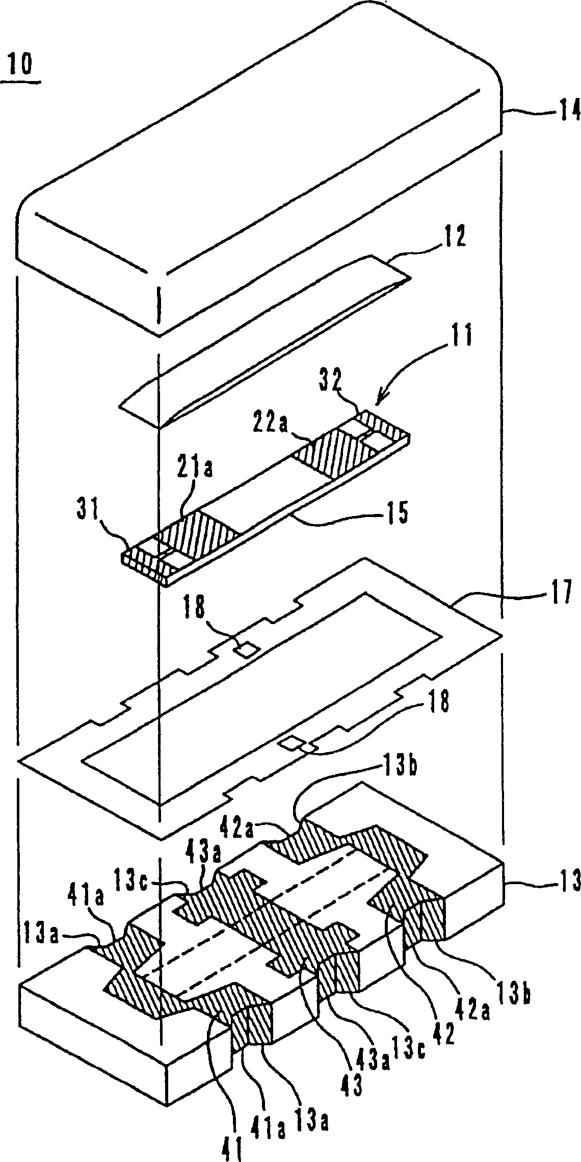
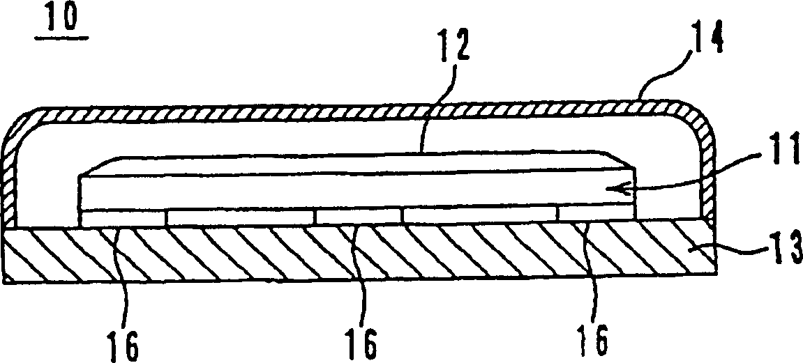
[0020] figure 1 A piezoelectric component of an embodiment of a wave trap according to the invention is shown in . The piezoelectric trap 10 includes a piezoelectric element 11 , a damper member 12 , a support substrate 13 for carrying the piezoelectric element 11 , and a cover member 14 for covering the piezoelectric element 11 on the support substrate 13 .
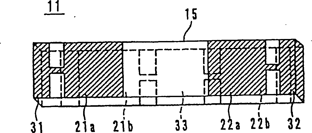
[0021] Such as figure 2 As shown, the piezoelectric element 11 contains such as Pb(Zr,Ti)O 3 (PZT) or the like rectangular piezoelectric substrate 15, two vibrating electrodes 21a and 22a are formed on the top surface of the piezoelectric substrate 15, and two vibrating electrodes 21b and 22b are formed on the bottom surface thereof. The vibrating electrodes 21b and 22b are opposed to the vibrating electrodes 21a and 22a, respectively, and sandwich the piezoelectric substrate 15 therebetween. On the left end portion of the piezoelectric substrate 15, a terminal electr...
no. 2 example
[0027] (Second embodiment, Figures 6 to 8 )
[0028] Image 6 A piezoelectric component according to an embodiment of the present invention is shown in , which is applied to a discriminator. The piezoelectric discriminator 50 includes a piezoelectric element 51 , a damper member 52 , a cover 53 for accommodating the piezoelectric element 51 , and a cover member 54 for shielding the opening of the top surface of the cover 53 .
[0029] The piezoelectric element 51 is formed of a rectangular piezoelectric substrate 55 having a vibration electrode 61 formed on its top surface, and a vibration electrode 62 formed on its bottom surface. The vibrating electrodes 61 and 62 are formed on the central portion of the piezoelectric substrate 55 so as to face each other. The extension portion 61a of the vibrating electrode 61 extends from the top surface to the bottom surface on the left end side of the piezoelectric substrate 55 . The extension portion 62a of the vibrating electrode ...
no. 3 example
[0034] (the third embodiment, Figure 9 with 10 )
[0035] Next, the third embodiment will be described based on a piezoelectric trap of a single body, such as Figure 9 As shown, a piezoelectric trap 70 includes a piezoelectric element 71, and protective substrates 74 and 75 for sandwiching the piezoelectric element 71 therebetween to form a vibration space.
[0036]The piezoelectric element 71 includes a piezoelectric substrate 80 having vibration electrodes 81a and 82a formed on the top surface thereof. On the bottom surface of the piezoelectric substrate 80, vibration electrodes 81b and 82b are formed so as to face the vibration electrodes 81a and 82a, respectively. In the left end portion of the piezoelectric substrate 80, an extension electrode 84 is formed, which is connected to the vibrating electrode 81a. In the right end portion of the piezoelectric substrate 80, an extension electrode 85 is formed, which is connected to the vibrating electrode 82a. Between the ...
PUM
 Abstract
Description
Claims
Application Information
 - R&D Engineer
- R&D Manager
- IP Professional
- Industry Leading Data Capabilities
- Powerful AI technology
- Patent DNA Extraction
Browse by: Latest US Patents, China's latest patents, Technical Efficacy Thesaurus, Application Domain, Technology Topic, Popular Technical Reports.
© 2024 PatSnap. All rights reserved.Legal|Privacy policy|Modern Slavery Act Transparency Statement|Sitemap|About US| Contact US: help@patsnap.com