Method for fitting zero phase sequence converter in leakage circuit breaker

A zero-phase-sequence converter and leakage circuit breaker technology, applied in circuits, inductors, electrical components, etc., can solve problems such as product quality differences, increased costs, and unstable relative positions.

Inactive Publication Date: 2004-05-19
FUJI ELECTRIC FA COMPONENTS & SYST CO LTD
View PDF0 Cites 0 Cited by
  • Summary
  • Abstract
  • Description
  • Claims
  • Application Information

AI Technical Summary

Problems solved by technology

[0006] 1. After placing the primary conductor 9 as Image 6 When bending into a U-shape as shown in (b), the zero-phase-sequence converter 8 will interfere with the processing, and the bending process cannot be performed with high precision.
[0007] 2. When performing the bending process of the primary conductor 9, the insulating tube 9b may be damaged
[0008] 3. Because the primary conductors 9R, 9S, and 9T of each phase running through the zero-phase-sequence converter 8 are not fixed in a certain position, their relative positions are unstable, so the balance characteristics will be different
[0013] 1. Because the primary conductors are divided into groups and each conductor is divided into blocks, and resin molding is performed on each block, the number of moldings is large, and the following operations must be performed: each block of the primary conductor after resin molding is changed to zero phase sequence After combining and connecting the flat conductor and the rod-shaped conductor, resin is used to seal the gap between the conductor junction and the through hole of the primary conductor of the zero-phase-sequence converter, so the number of assembly processes increases and the cost increases
[0014] 2. In the above 1, the joint between the conductors and the resin sealing of the primary conductor through-hole of the zero-phase-sequence converter are manually operated, so it is difficult to fill the resin into the rod-shaped conductor and the zero-phase-sequence converter. Every corner between the through holes of the converter does not leave a little gap. Due to the gap between the sealing resin and the primary conductor and the zero-phase sequence converter and the remaining gaps in the resin layer, the insulation performance is reduced. The quality is prone to variance

Method used


Image

  • Method for fitting zero phase sequence converter in leakage circuit breaker
  • Method for fitting zero phase sequence converter in leakage circuit breaker
  • Method for fitting zero phase sequence converter in leakage circuit breaker

Examples


Embodiment Construction

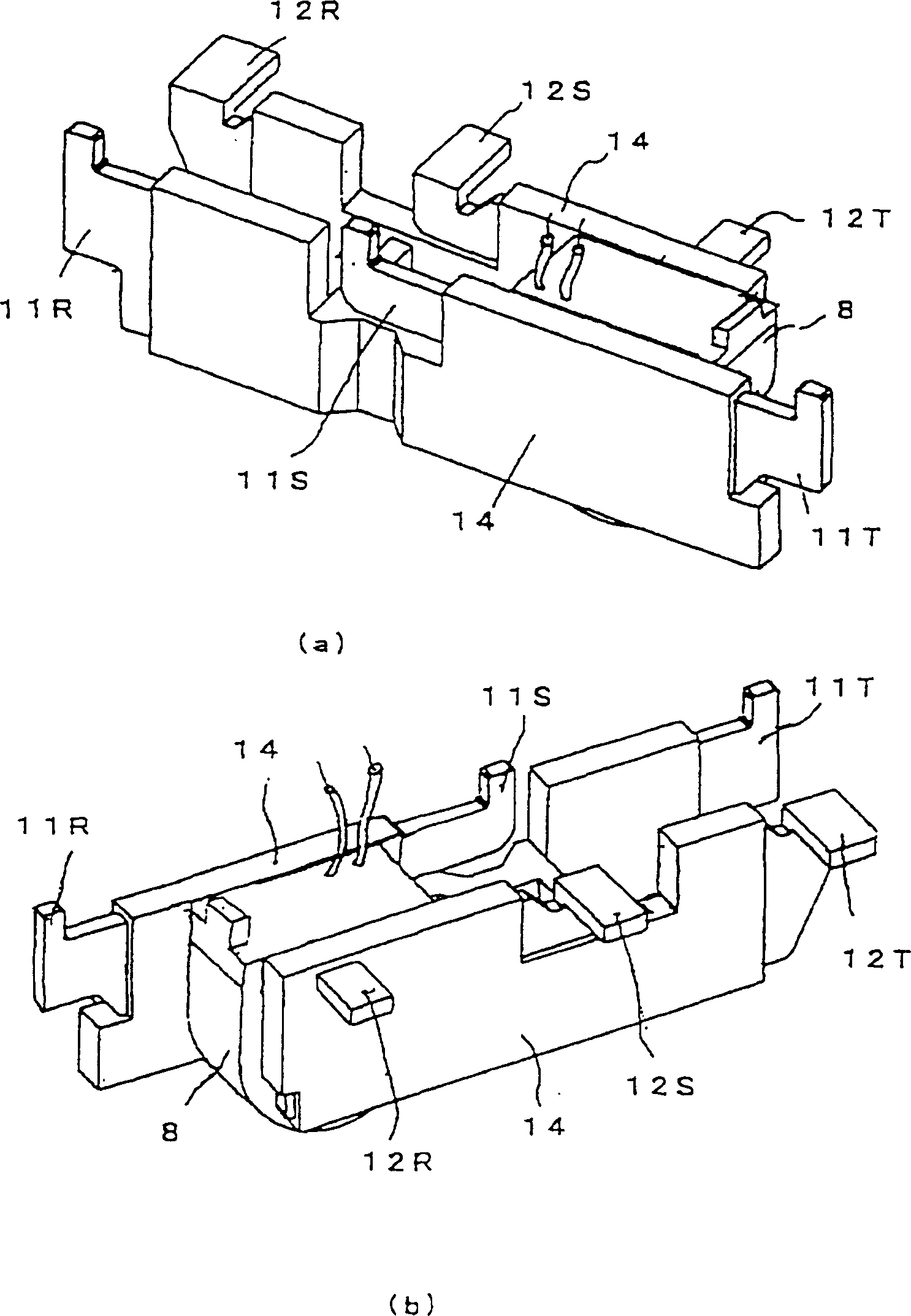
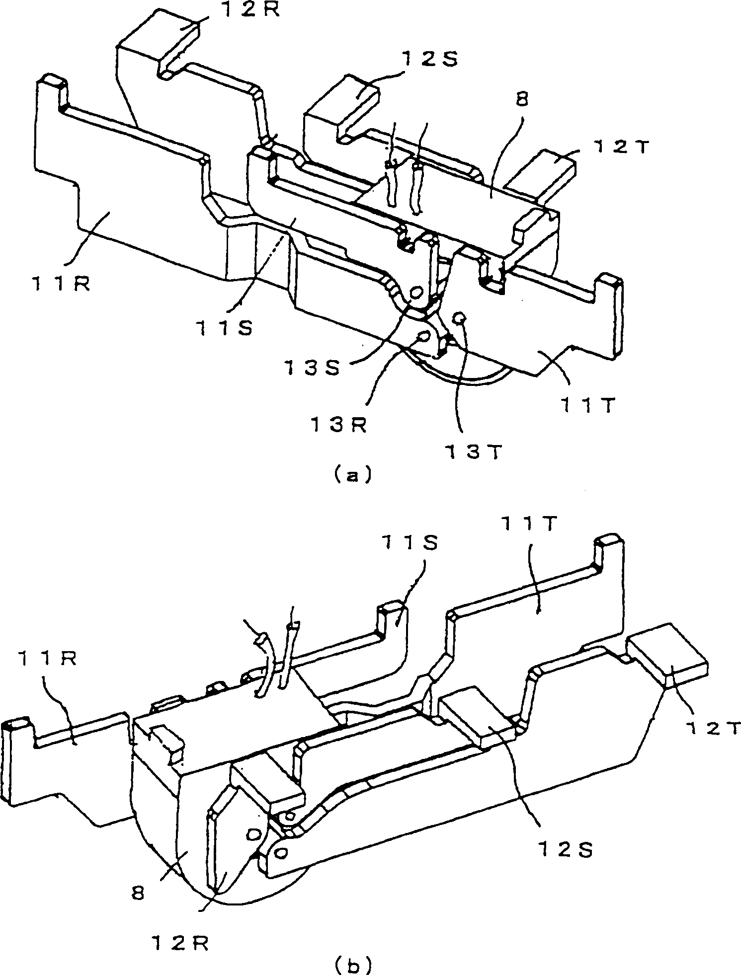
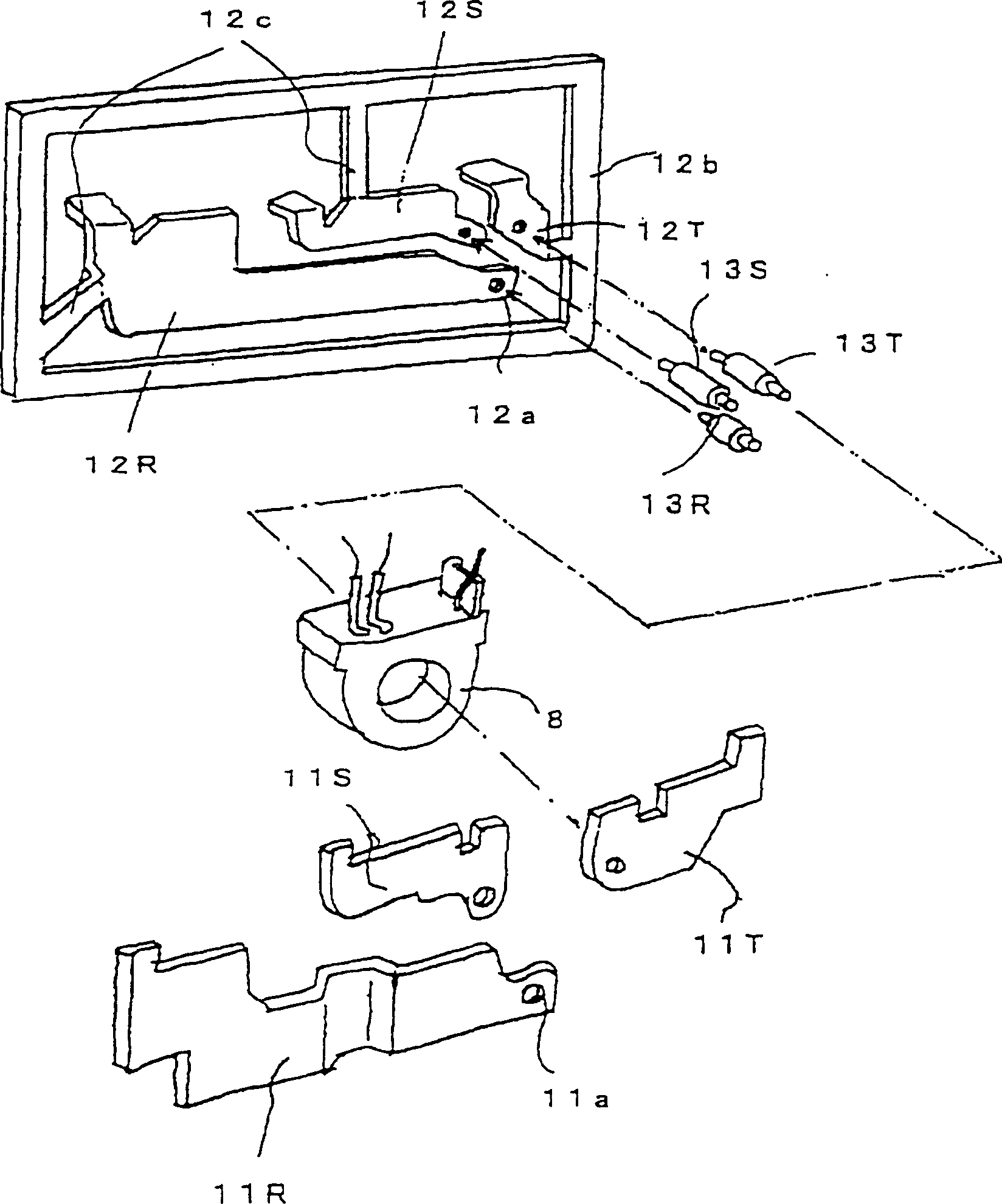
[0027] based on the following Figure 1-Figure 4 The illustrated examples illustrate embodiments of the invention.

[0028] In the attached picture, figure 1 (a) and (b) show the appearance of the finished product of the zero-phase-sequence converter unit, figure 2 (a) and (b) show the appearance of the tentative assembled state before the resin molding process, image 3 Shown is an exploded view of the individual parts at the stage prior to provisional assembly, Figure 4 (a)-(c) shows the structure diagram of the zero-phase-sequence converter. In addition, in each figure, 8 is a zero-phase-sequence converter, 11R, 11S, 11T and 12R, 12S, 12T are respectively arranged on both sides of the zero-phase-sequence converter 8, and R, S, T The flat conductors of each corresponding primary conductor, 13R, 13S, 13T pass through the primary conductor through hole 8a of the zero-phase sequence converter 8 and connect the flat conductors 11R, 11S, 11T with 12R, 12S, 12T Connection,...


PUM


Abstract

Disclosed is an assembling method for a zero phase current transformer which is able to secure stable quality and yield in addition to cutting down a resin molding process. A primary conductor is composed of a three-phase flat conductors which are distributed on the same plane on both sides of the zero phase current transformer 8, and the rod conductors which are bonded between the flat conductors by penetrating through the primary conductor through holes of the zero phase current transformer. A unit is temporarily assembled by bonding both ends of the rod conductor that penetrates through the zero phase current transformers to the flat conductors placed side by side at fixed positions, with each conductor of the primary conductor left as a bare conductor. After that, the surrounding area of the temporarily assembled body of the unit, which includes the inside of the conductor through hole and the bonded part between the conductors, is collectively and integrally molded by a resin through the use of an injection molding method.

Description

technical field [0001] The invention relates to an assembly method of a zero-phase-sequence converter unit installed in an earth leakage circuit breaker for power distribution. Background technique [0002] first, Figure 5 The structure of the earth leakage circuit breaker (for three-phase) mentioned above is shown. In the figure, 1 is the circuit breaker housing divided into two parts, 2 is the power supply side terminal of the main circuit, 3 is the load side terminal, 4 is the fixed contact, 5 is the moving contact, 6 is the opening and closing operation handle , 7 is the over-current tripping unit, 8 is the zero-phase-sequence converter, and the primary conductors 9 of each phase running through the zero-phase-sequence converter 8 are connected in the housing to the corresponding main conductors assembled in the housing 1. circuit components. In addition, 10 is a printed circuit board of the leakage current detection circuit. [0003] Here, refer to Figure 6 (a) an...

Claims


Application Information

Patent Timeline
IPC IPC(8): H01F38/28H01H69/00H01H83/02H01H83/14
CPCH01F38/28H01H69/00H01H83/02H01H83/14
Inventor 横森则晴川嶋善明古川雅晴富田义雄
Owner FUJI ELECTRIC FA COMPONENTS & SYST CO LTD
Why Eureka
Try Eureka