
Motor adhesive iron core manufacturing device and manufacturing method thereof

A manufacturing device and glue technology, which is applied to the motor viscose iron core manufacturing device and its manufacturing field, can solve the problems of low production efficiency, inconsistent glue thickness, and affecting enterprise benefits, etc., and achieve high production effect and firm and reliable bonding Effect

Active Publication Date: 2022-08-09
苏州范斯特机械科技有限公司
View PDF11 Cites 3 Cited by
  • Summary
  • Abstract
  • Description
  • Claims
  • Application Information

AI Technical Summary

Problems solved by technology

[0002] The viscose iron cores that appear on the market today, especially the viscose iron cores of new energy vehicle drive motors, still need to be heated inside or outside the mold or other auxiliary heating methods at room temperature (10°C-40°C) , so that the punched and formed sheets are cured and bonded together to form a fixed iron core (that is, the stator of the motor) or a moving iron core (that is, the rotor of the motor); The method of in-mold heating-assisted curing is based on the use of high-temperature heating. However, high-temperature heating requires a period of time to achieve complete curing, and the curing time required by this method is 3-5 minutes, so the production efficiency is extremely low. Specifically Please refer to the patent document CN108233643A which discloses a method for making iron cores by punching motor sheets; and the amount of glue sprayed by each nozzle cannot be controlled, resulting in inconsistent glue spray volumes each time, resulting in inconsistent thickness of glue between the iron chips. As a result, the working performance of the formed iron core cannot meet the requirements, resulting in more defective products, resulting in waste of materials, seriously affecting the profitability of the enterprise, and seriously restricting the vigorous promotion of viscose iron cores in new energy vehicle motors

Method used


Image

  • Motor adhesive iron core manufacturing device and manufacturing method thereof
  • Motor adhesive iron core manufacturing device and manufacturing method thereof
  • Motor adhesive iron core manufacturing device and manufacturing method thereof

Examples


Embodiment

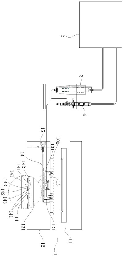
[0049] like figure 1 and figure 2 As shown, a device for manufacturing a motor viscose iron core described in this embodiment includes a continuous blanking die 1 and an accelerator spraying station 5 located at the entry end of the material strip of the continuous blanking die 1. The continuous blanking die 1 sequentially includes The forming station 1 102 for forming the notch forming hole 1 112, the notch forming hole 2 113 and the stator square slot 111, the forming station 2 103 for forming the ventilation hole 114 and the notch forming hole 3 125, for the rotor magnetic steel Slot 115, rotor shaft hole 116 and forming station 3 104 for re-forming the stator square slot 111, glue spraying station 1 105 with glue spraying mechanism 13, blanking station 106 for forming rotor iron core 118, with Forming station four 107 for forming slot-shaped holes 120 and elongated holes 122, forming station five 108 for forming stator grooves and stator shaft holes, and glue spraying st...


PUM


Abstract

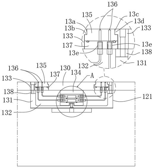
The invention discloses a motor adhesive iron core manufacturing device and a manufacturing method thereof. The motor adhesive iron core manufacturing device comprises a continuous blanking die, and the continuous blanking die comprises at least one blanking station and an adhesive spraying mechanism located in front of the at least one blanking station; the glue spraying mechanism comprises a containing cavity located in the lower die, a pulling plate cushion block located in the containing cavity and a glue spraying module located at an opening of the containing cavity, the glue spraying module is fixed to the pulling plate cushion block, and a plurality of glue spraying annular areas are formed on the glue spraying module; a plurality of nozzles arranged in an annular array and transmission channels in butt joint with the nozzles are formed in each glue spraying annular area, a concave cavity is formed in the pulling plate cushion block, a flow dividing module is installed in the concave cavity, and the motor adhesive iron core manufacturing device is used for manufacturing a rotor iron core and a stator iron core, so that the production efficiency is improved, and the production cost is reduced. And the quality of the produced iron core is improved.

Description

technical field [0001] The invention relates to the technical field of iron core manufacturing in electric motors for new energy vehicles, in particular to a manufacturing device and a manufacturing method of a motor viscose iron core. Background technique [0002] The viscose iron cores that appear on the market, especially the viscose iron cores of the drive motors of new energy vehicles, still need to be heated in or outside the mold or use other auxiliary heating methods at normal temperature (10°C-40°C). , so that the blanked sheets are cured and bonded together to form a fixed iron core (that is, the stator of the motor) or a moving iron core (that is, the rotor of the motor). The method of in-mold heating-assisted curing is based on the use of high-temperature heating. However, high-temperature heating requires a period of aging to achieve complete curing, and the curing time required by this method is 3-5 minutes, so the production efficiency is extremely low. See p...

Claims


Application Information

Patent Timeline
Patent Type & Authority Applications(China)
IPC IPC(8): H02K15/03H02K15/12B05C5/02B05C11/10
CPCH02K15/03H02K15/12B05C5/027B05C11/1002B05C5/0212H02K2213/03Y02T10/64
Inventor 周茂伟蒋宁黄秀东邹春华钟丽祝石伟磊
Owner 苏州范斯特机械科技有限公司
Learn More