
Energy-saving heat exchange equipment based on wastewater discharge

A technology for heat exchange equipment and wastewater discharge, applied in the field of heat exchange, can solve problems such as the influence of heat exchange efficiency of heat exchange equipment, accumulation of impurities on the inner wall of heat exchange equipment, and complex mechanism of heat exchange equipment, so as to improve heat exchange efficiency and enhance barriers effect, the effect of prolonging the heat exchange time

Pending Publication Date: 2022-08-09
蔡金榜
View PDF0 Cites 0 Cited by
  • Summary
  • Abstract
  • Description
  • Claims
  • Application Information

AI Technical Summary

Problems solved by technology

[0003] Nowadays, many chemical wastewater generally have a fixed temperature range, resulting in high heat energy in the waste water that has completed the reaction, and direct discharge will lead to waste of resources. Generally, heat exchange equipment is used to replace the heat energy inside the waste water for a long time. After use, impurities will accumulate on the inner wall of the heat exchange equipment. If it is not cleaned in time, it will affect the heat exchange efficiency of the heat exchange equipment. However, the mechanism of the heat exchange equipment is relatively complicated and the maintenance cost is high. Therefore, we propose a A kind of energy-saving heat exchange equipment based on wastewater discharge is used to solve the above problems

Method used


Image

  • Energy-saving heat exchange equipment based on wastewater discharge
  • Energy-saving heat exchange equipment based on wastewater discharge
  • Energy-saving heat exchange equipment based on wastewater discharge

Examples


Embodiment Construction

[0035]The technical solutions in the embodiments of the present invention will be clearly and completely described below with reference to the accompanying drawings in the embodiments of the present invention. Obviously, the described embodiments are only a part of the embodiments of the present invention, but not all of the embodiments. Based on the embodiments of the present invention, all other embodiments obtained by those of ordinary skill in the art without creative efforts shall fall within the protection scope of the present invention.

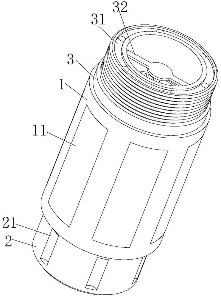
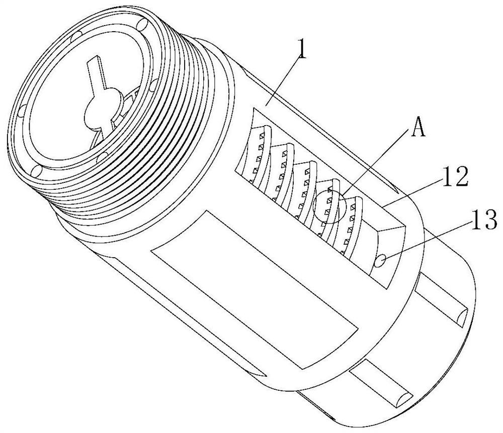
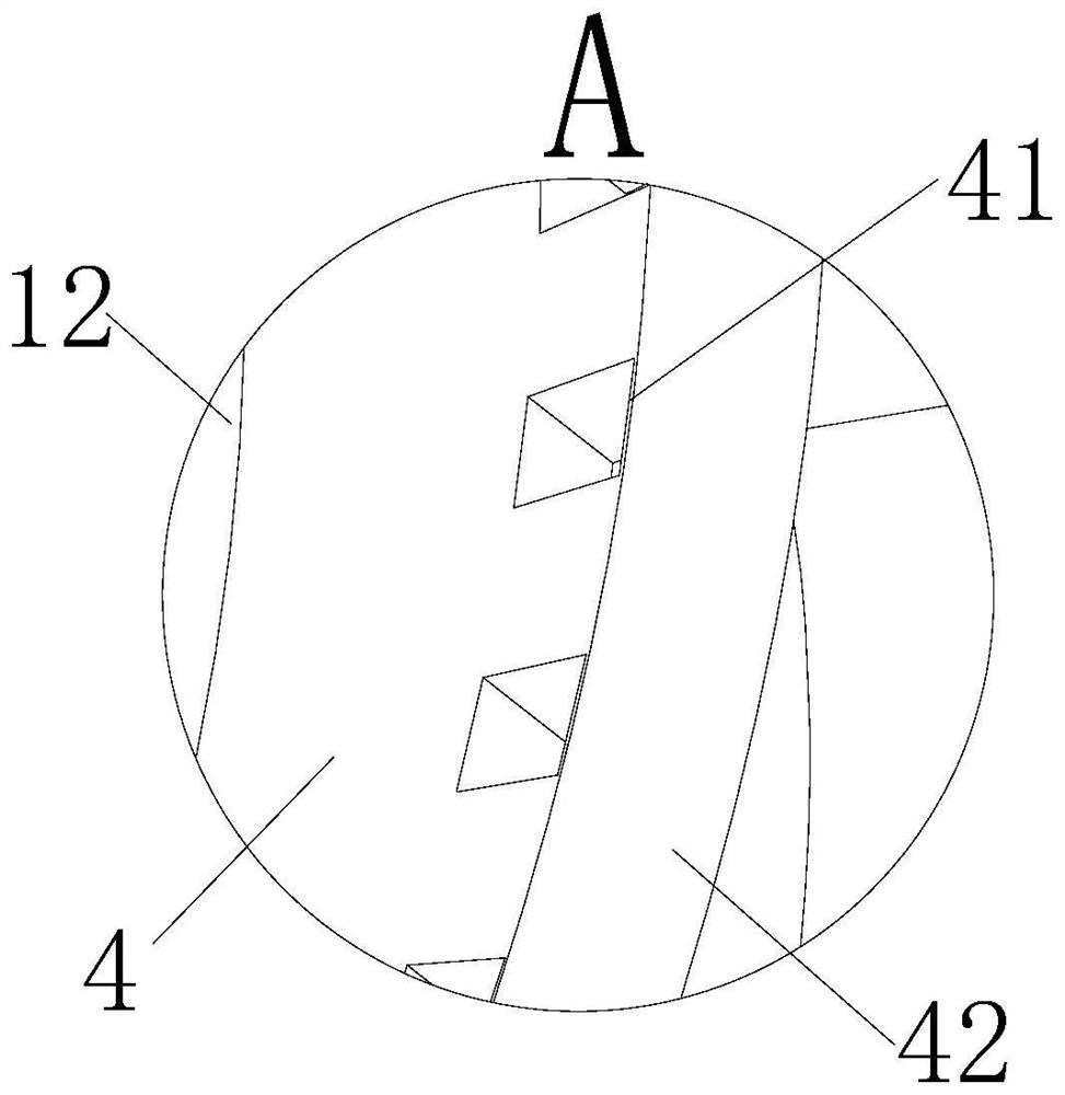
[0036] see Figure 1-8 , the present invention provides a technical solution: an energy-saving heat exchange device based on waste water discharge, comprising a fixed pipe 1, a fixed ring 2 is fixedly connected to one side of the fixed pipe 1, and a plurality of clamping grooves 21 are opened on the surface of the fixed ring 2, The clamping grooves 21 are arranged in an annular array on the surface of the fixing ring 2. The fixing ring...


PUM


Abstract

The energy-saving heat exchange equipment comprises a fixed pipeline, a fixed ring is fixedly connected to one side of the fixed pipeline, a plurality of clamping grooves are formed in the surface of the fixed ring, the clamping grooves are formed in the surface of the fixed ring in an annular array mode, a water drainage opening is formed in the fixed ring, and a connecting ring is fixedly connected to the other end of the fixed pipeline; external threads are arranged on the outer wall of the connecting ring, a limiting groove is formed in one end of the connecting ring, a plurality of water inlet holes are formed in the limiting groove, and a supporting rod is fixedly connected to the inner wall of the limiting groove; compared with the prior art, when sewage passes through the driving shaft, the driving shaft can be driven to rotate under the action of a driving piece, and in the rotating process of the driving shaft, under the action of a fixed shaft and a movable groove, the driving shaft can reciprocate back and forth, and the flow direction of the sewage can be intermittently changed; the heat exchange time of sewage can be prolonged, and meanwhile, the sewage can be stirred, so that the condition of non-uniform sewage temperature is avoided.

Description

technical field [0001] The invention relates to the technical field of heat exchange, in particular to an energy-saving heat exchange device based on waste water discharge. Background technique [0002] Heat exchange is the process of heat transfer between two objects or parts of the same object due to temperature differences. Heat exchange is generally accomplished in three ways: heat conduction, heat convection and heat radiation. Heat exchange is also called heat exchange. A process in which thermal energy is transferred from a hot fluid indirectly (eg through a partition) or directly to a cold fluid. [0003] Nowadays, many chemical wastewaters generally have a fixed temperature range, which leads to high thermal energy inside the wastewater after the reaction is completed. Direct discharge will lead to waste of resources. Generally, the thermal energy inside the wastewater is replaced by heat exchange equipment. After use, it will lead to the accumulation of impuriti...

Claims


Application Information

Patent Timeline
Patent Type & Authority Applications(China)
IPC IPC(8): F28D21/00F28F13/12F28F19/01F28G1/00C02F9/10
CPCF28D21/0012F28F13/125F28F19/01F28G1/00C02F1/00C02F1/001C02F2303/14Y02B30/56
Inventor 蔡金榜
Owner 蔡金榜
Learn More