
Tunnel waterproof structure and method

A technology for waterproof structures and tunnels, which is applied in tunnels, tunnel linings, earthwork drilling and mining, etc. It can solve problems such as flash welding, unable to arch wall coils, water leakage, etc., achieve convenient grouting, improve waterproof effect, and Good pulp effect

Pending Publication Date: 2022-08-09
BEIJING ORIENTAL YUHONG WATERPROOF TECH CO LTD
View PDF0 Cites 0 Cited by
  • Summary
  • Abstract
  • Description
  • Claims
  • Application Information

AI Technical Summary

Problems solved by technology

[0002] Tunnel waterproofing has always been a key link in tunnel construction. Tunnel waterproofing includes waterproofing construction on multiple nodes. T”-shaped lap joints, in view of the fact that most tunnel coils are welded with double seams, the double seam welding machine is wedged between the upper and lower coils to heat the coils, the rollers climb and weld by themselves, and generate extrusion force, so that The upper and lower coils in the molten state are bonded together, but since the welding roller of the welding machine must keep a certain distance from the edge of the coils during welding, no adhesion will occur at the outer edge of the welding of the upper and lower coils at this part, forming What we commonly call flashing, when the arch wall coil with flash is overlapped and then stubbled with the inverted arch coil, the hot wedge of the welding machine is heated on the upper surface of the lower coil, which cannot make the weld seam of the arch wall coil The flash welding on the outside will lead to a channel for water channeling in this part, and it is very easy to leak water in this part in the later stage of the tunnel.

Method used


Image

  • Tunnel waterproof structure and method
  • Tunnel waterproof structure and method
  • Tunnel waterproof structure and method

Examples


Embodiment

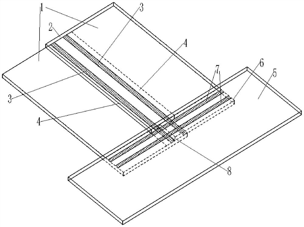
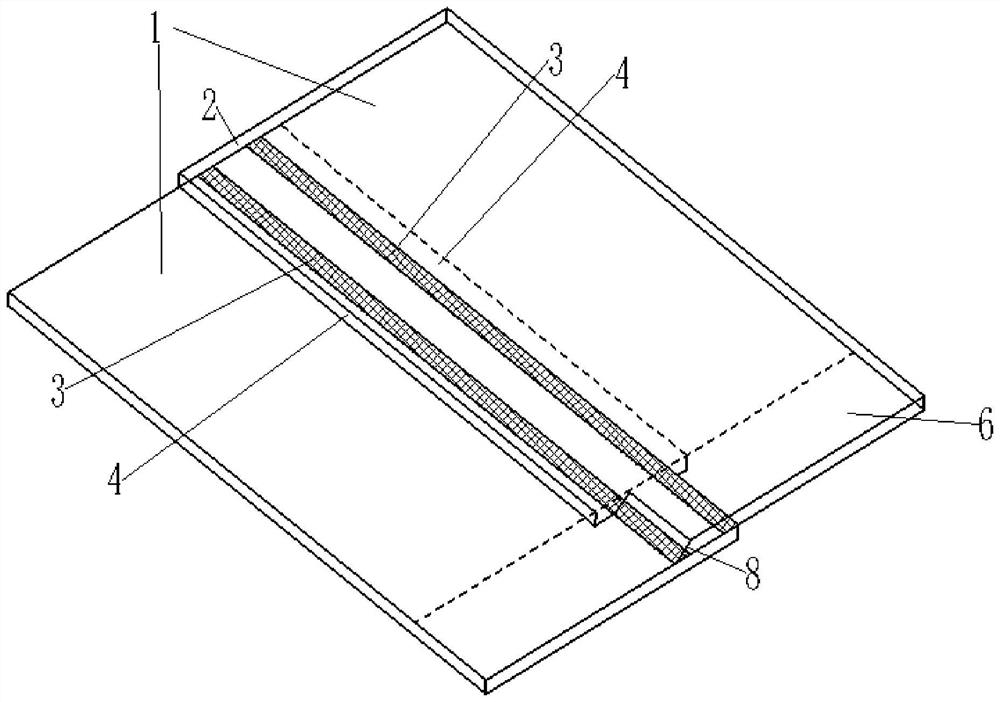
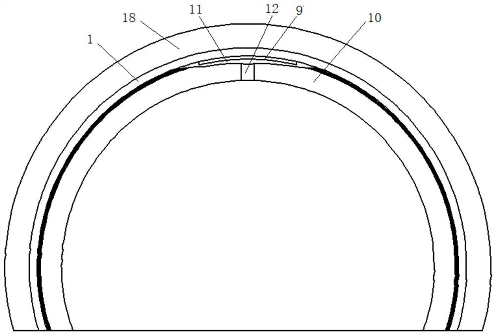
[0105] like Figure 1 to Figure 7 As shown, the present invention provides a tunnel waterproof structure, the waterproof structure includes:

[0106] The first waterproof coiled material 1 is laid on the tunnel arch wall, and two adjacent first waterproof coiled materials 1 are overlapped by their first overlapping edges 2, and the two overlapping first overlapping edges 2 are overlapped with each other. Connected by the first bar-shaped welding portion 3, the first waterproof membrane 1 forms a flash portion 4 on the outer side of the first bar-shaped welding portion 3;

[0107] The second waterproof coiled material 5 is laid on the inverted arch of the tunnel and overlapped with the second lap edge 6 of the first waterproof coiled material 1, and the second waterproof coiled material 5 and the second lapped edge 6 pass through the second The second strip welding part 7 is perpendicular to the first strip welding part 3;

[0108] The flash portion 4 between the second overl...


PUM


Abstract

The invention discloses a tunnel waterproof structure and method, and relates to the technical field of tunnel waterproofness, the tunnel waterproof structure comprises first waterproof coiled materials laid on a tunnel arch wall, two adjacent first waterproof coiled materials are in lap joint through first lap joint edges of the first waterproof coiled materials, the two first lap joint edges in lap joint are connected through a first strip-shaped welding part, and a second strip-shaped welding part is arranged between the first strip-shaped welding part and the second strip-shaped welding part; the first waterproof coiled material forms a flash part on the outer side of the first strip-shaped welding part; the second waterproof roll is laid on the tunnel inverted arch and is in lap joint with the second lap joint edge of the first waterproof roll, the second waterproof roll is connected with the second lap joint edge through a second strip-shaped welding part, and the second strip-shaped welding part is perpendicular to the first strip-shaped welding part; a flash part between the second overlap edge and the second waterproof coiled material is cut off; when the first waterproof coiled material and the second waterproof coiled material are overlapped, the flash part between the second overlapping edge and the second waterproof coiled material is cut off, so that the first strip-shaped welding part is exposed, a water channeling channel formed by the flash part is eliminated when the first waterproof coiled material and the second waterproof coiled material are overlapped, and the waterproof effect at the T-shaped node is improved.

Description

technical field [0001] The invention belongs to the technical field of tunnel waterproofing, and more particularly, relates to a tunnel waterproofing structure and method. Background technique [0002] Tunnel waterproofing has always been a key link in tunnel construction. Tunnel waterproofing includes waterproofing construction on multiple nodes. For example, when the inverted arch stubble coil of the current waterproof board in the tunnel overlaps with the arch wall stubble coil, a "" T”-shaped lap joints, since most of the tunnel coils are welded by double seam, the double seam welder is hot wedged between the upper and lower coils, heating the coils, the rollers climb and weld on their own, and generate extrusion force, making the The upper and lower two coils in the molten state are bonded together, but due to the inevitable distance between the welding machine roller and the edge of the coil during welding, there will be no adhesion at the outer edge of the upper and l...

Claims


Application Information

Patent Timeline
Patent Type & Authority Applications(China)
IPC IPC(8): E21D11/38
CPCE21D11/38E21D11/383Y02E10/20
Inventor 王超群
Owner BEIJING ORIENTAL YUHONG WATERPROOF TECH CO LTD
Learn More