Label production equipment with film covering function
A technology of production equipment and functions, applied in the field of label production equipment with lamination function, can solve the problems of tensile deformation, paper or film wrinkles, insufficient tension of guide rollers, etc.
- Summary
- Abstract
- Description
- Claims
- Application Information
AI Technical Summary
Problems solved by technology
Method used
Image
Examples
Embodiment 1
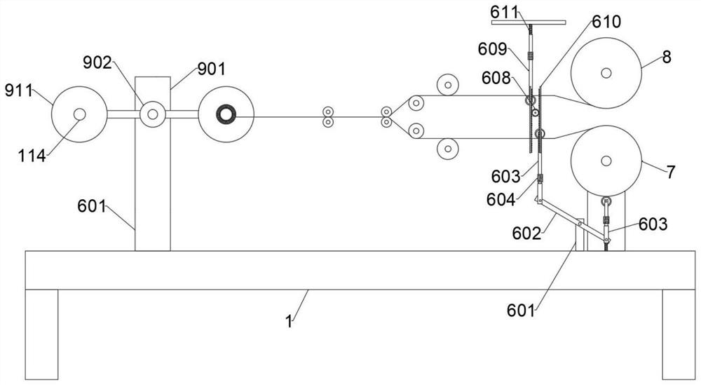
[0034] The surface of the existing label is generally attached with a film. The finished label is made of semi-finished paper and film bonded by glue. The semi-finished paper and film are generally wound into rolls with a large diameter on the outside of the drum. The number of processed labels can be greatly increased, and then the paper and film are extruded into labels with films through multiple rollers and other devices. Gradually decrease, because the position of the drum and the guide roller of the existing label processing device is not adjustable, and then the paper and film will be separated from the guide roller as the diameter of the paper and film wound on the outside of the drum gradually decreases. The tension between the two is gradually reduced, and the paper and the film are gradually changed from tension to relaxation. There is a problem of folds after the intermediate synthesis;
[0035] And in the early stage of the rolled paper and film being processed, ...
Embodiment 2
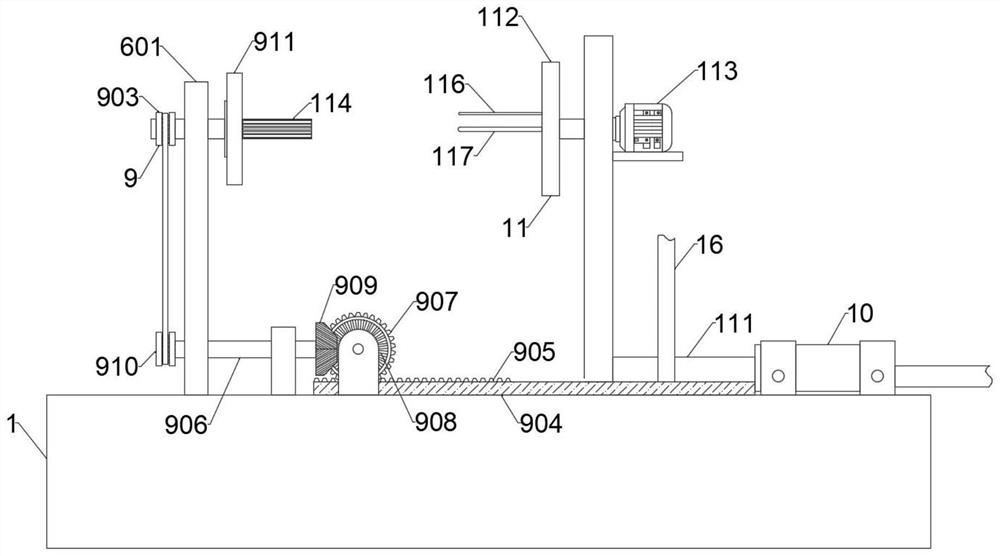
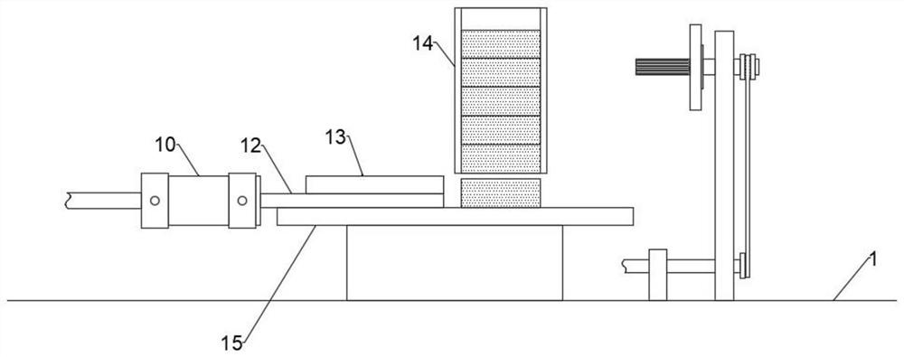
[0040] The paper and film rolls are made into labels with films through the existing device, and the paper rolls roll the already made labels. After the paper rolls are rolled to a certain extent, the corresponding pneumatic push cylinder 10 is activated, The pneumatic push cylinder 10 pushes the push rod 1 904 and the cutting frame 16 fixedly connected to the top thereof. A cutter is installed at one end of the cutting frame 16. The pneumatic push cylinder 10 pushes the push rod 1 904 to slide in the cutting guide rail 17. During this process , a rack 2 905 is installed on the top of the push rod 1 904, a chute 4 912 is opened on the top of the push rod 1 904, the rack 2 905 is slidably connected in the chute 4 912, and the top of the rack 1 is fixedly connected with a guide plate 913, the guide plate 913 is matched with the rack 2 905, the corresponding pneumatic push cylinder 10 pushes the push rod 1 904 to move, the spur gear 2 907 is fixedly connected to one side of the he...
Embodiment 3
[0042] After the cutter cuts off the label, the corresponding pneumatic push cylinder 10 will pull the push rod 1 904 to move in the reverse direction. 907 engages and rotates, causing the problem that the turntable 902 included in the flip assembly 9 rotates 180 degrees in the opposite direction. There is a fourth chute 912 on the top of the push rod 1 904, and a rack 2 905 is slidably connected in the chute 4 912. A guide plate 913 is installed inside the frame 1, so that when the push rod 1 904 moves with the rack 2 905, it first meshes with the spur gear 2 907 and completes the transmission, that is, after the turntable 902 rotates 180 degrees, the push rod The first 904 continues to move until the guide plate 913 pushes the rack two 905 from one side of the chute four 912 to the other side, so that when the push rod one 904 moves in the reverse direction, the rack two 905 cannot connect with the spur gear two 907 After the second rack 905 passes through the second spur ge...
PUM
 Abstract
Description
Claims
Application Information
 - R&D Engineer
- R&D Manager
- IP Professional
- Industry Leading Data Capabilities
- Powerful AI technology
- Patent DNA Extraction
Browse by: Latest US Patents, China's latest patents, Technical Efficacy Thesaurus, Application Domain, Technology Topic, Popular Technical Reports.
© 2024 PatSnap. All rights reserved.Legal|Privacy policy|Modern Slavery Act Transparency Statement|Sitemap|About US| Contact US: help@patsnap.com


