Solar photo-thermal coupling phase conversion carbon dioxide reduction catalytic reaction system and method

A light-thermal coupling and carbon dioxide technology, applied in chemical instruments and methods, separation methods, energy input, etc., can solve problems such as discontinuity of solar energy, unstable influence of solar climate and meteorological conditions, and constant difficulty of sunlight temperature, etc. To achieve the effects of effective illumination and stability promotion, effective illumination and good stability, airtightness and light transmission

Active Publication Date: 2022-08-09
XI AN JIAOTONG UNIV
View PDF7 Cites 0 Cited by
  • Summary
  • Abstract
  • Description
  • Claims
  • Application Information

AI Technical Summary

Problems solved by technology

[0004] However, due to the discontinuity of solar energy and the instability of climate and meteorological conditions, the existing solar photothermal coupled catalytic reactors have many deficiencies
(1) The instability of sunlight will make it difficult to keep the temperature in the reactor constant, and the temperature not only determines the phase of the reactants, but also plays an important role in the photothermal coupling catalyzed CO2 reduction reaction. The rate also has a great influence; (2) The photothermal coupling catalytic reaction is often accompanied by the increase of the system pressure, which poses a greater challenge to the design and optimization of the material inlet and outlet; (3) Due to the discontinuity of solar energy, the traditional The solar photothermal reactor can only be used intermittently, which causes system instability and increases the difficulty of time management for operators; (4) The feed ratio of reactants is very important for photothermal coupling catalytic CO2 reduction The product selectivity and yield of the reaction have a great influence, and the feeding method in the traditional photothermal coupling catalytic system cannot accurately control the feeding amount of CO2 and water, and cannot precisely control a single product (5) The extensiveness of sunlight and the influence of buildings and the surrounding environment have high requirements for the construction of the system, the layout of the site and the distribution of light paths

Method used


Image

  • Solar photo-thermal coupling phase conversion carbon dioxide reduction catalytic reaction system and method
  • Solar photo-thermal coupling phase conversion carbon dioxide reduction catalytic reaction system and method
  • Solar photo-thermal coupling phase conversion carbon dioxide reduction catalytic reaction system and method

Examples


Embodiment 1

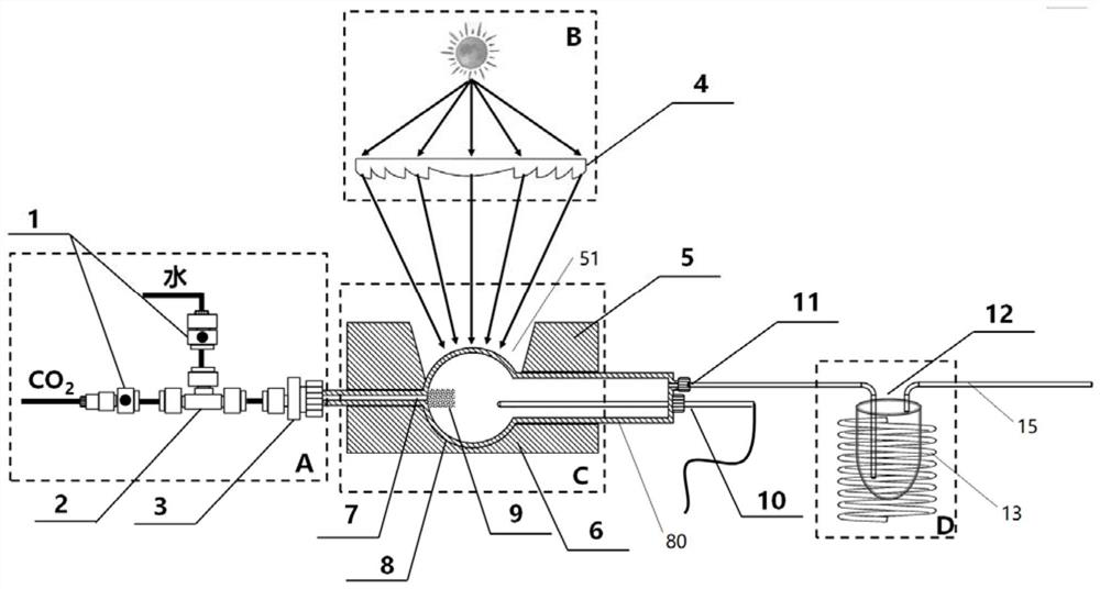
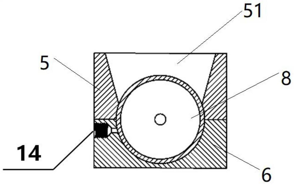
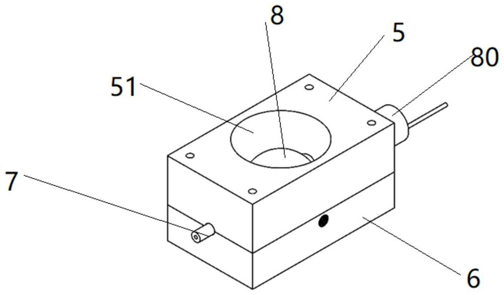
[0039] see Figure 1 to Figure 3 As shown, a solar-photothermal coupled phase conversion carbon dioxide reduction catalytic reaction system includes a feeding device A, a Fresnel lens concentrating device B, a high temperature phase inversion reaction device C and a product cooling analysis device D. Wherein the feeding device A, the high temperature phase inversion reaction device C and the product cooling analysis device D are connected through a conduit.

[0040] The feeding device A mainly includes: a flow control system 1, a T-type gas-liquid mixing valve 2 and a gas-liquid mixture dispersion system 3; the two input ends of the T-type gas-liquid mixing valve 2 are respectively connected to a water input pipe and a carbon dioxide input pipe; the water input pipe A flow control system 1 is provided on each of the carbon dioxide and carbon dioxide input pipes. The output end of the T-type gas-liquid mixing valve 2 is connected to the input end of the high temperature phase ...

Embodiment 2

[0050] The invention provides a solar photothermal coupled phase conversion carbon dioxide reduction catalytic reaction, comprising the following steps:

[0051] water and CO 2 The gas enters the T-type gas-liquid mixing valve 2 through the flow control system 1 of each branch, thereby determining the water / CO of the reaction system. 2 Proportion. while water and CO 2 The gas enters the gas-liquid mixture dispersion system 3 in the form of a gas-liquid mixture after passing through the T-type gas-liquid mixing valve 2, and enters the phase inversion preheating pipe 7 through atomization and dispersion. The gas-liquid mixture passing through the phase inversion preheating tube 7 is formed to uniformly disperse water vapor and CO 2 The gas form is sprayed into the high temperature reaction zone 8 through the porous steam spray head 9 to participate in the reaction. The product is introduced into the product cooling analysis device D through the gas outlet 11, wherein the liq...

Embodiment 3

[0054] In this example, a solar photothermal coupled phase conversion carbon dioxide reduction catalytic reaction system of the present invention is used for Co 3 O 4 Loaded CuO x Thin-film Photothermal Catalysts Solar Photothermal Coupled Catalysis of CO 2 Reduction reaction: 1x1cm size Co 3 O 4 / CuO x The thin film photothermal catalyst is placed in the spherical reaction zone 81 . CO control via gas flow meter 2 The flow rate is 10sccm, the flow rate of the water controlled by the syringe pump is 20mL / min, the inner diameter of the phase conversion preheating pipe 7 is 1mm, and the length of the phase conversion preheating pipe 7 placed in the heating zone is 6mm; The inner wall ball diameter is 15mm, the porous steam jet head 9 is sintered integrally with the phase conversion preheating tube 7, the diameter is the same as the phase conversion preheating tube, the length is 1.2 times the diameter, and the pore size is 50nm; the built-in thermocouple 10 is T-shaped , ...


PUM


Abstract

The invention belongs to the field of solar energy conversion and utilization, and discloses a solar energy photo-thermal coupling phase conversion carbon dioxide reduction catalytic reaction system and method. The system comprises a feeding device used for feeding reactants into a high-temperature phase conversion reaction device; the heat supply device is used for supplying all / part of reaction heat to the high-temperature phase conversion reaction device; the high-temperature phase conversion reaction device comprises a heat preservation heating jacket, a compensation heating jacket and a reactor, the reactor is arranged between the heat preservation heating sleeve and the compensation heating sleeve; the reactor comprises a phase conversion preheating pipe, a spherical reaction area and a tail pipe which are connected in sequence. On the basis of ensuring high-precision testing, the high-integration and automatic design can effectively reduce the cost of sites, materials, labor and the like. The device is wide in application range, high in sunlight utilization rate, high in CO2 reduction reaction efficiency and capable of achieving full-spectrum solar-driven photo-thermal coupling catalysis CO2 reduction reaction.

Description

technical field [0001] The invention belongs to the field of solar energy conversion and utilization, and in particular relates to a solar photothermal coupled phase conversion carbon dioxide reduction catalytic reaction system and method. Background technique [0002] The transformation of energy and power technology can directly promote the leap-forward development of human civilization and social economy. Mastering revolutionary and leading energy and power technology and industrial technology is the basic and necessary condition for the rise of all world powers and leading world development in history. Today's excessive consumption of fossil energy by humans has caused urgent problems such as climate change, energy crisis and environmental pollution. In the natural carbon cycle, CO in the atmosphere 2 Absorbed by plants and then returned to the atmosphere through biological or geological processes, it is always in a dynamic equilibrium. However, with the rapid developm...

Claims


Application Information

Patent Timeline
IPC IPC(8): B01D53/86B01D53/62
CPCB01D53/86B01D53/62B01D53/8696B01D2257/504Y02P20/133
Inventor 郭烈锦白生杰余方博刘亚王峰
Owner XI AN JIAOTONG UNIV
Why Eureka
Try Eureka