Creation method and apparatus of network configuration for power system

A network configuration and power system technology, applied in the direction of AC and DC network circuit layout, circuit devices, system integration technology, etc., can solve problems such as longer calculation time and increased number

Inactive Publication Date: 2004-05-05
HITACHI LTD
View PDF0 Cites 0 Cited by
  • Summary
  • Abstract
  • Description
  • Claims
  • Application Information

AI Technical Summary

Problems solved by technology

Therefore, candidates to be estimated increase in number, and calculation time becomes long

Method used


Image

  • Creation method and apparatus of network configuration for power system
  • Creation method and apparatus of network configuration for power system
  • Creation method and apparatus of network configuration for power system

Examples


Embodiment Construction

[0022] Embodiments of the present invention will be explained below with reference to FIGS. 1 to 8 .

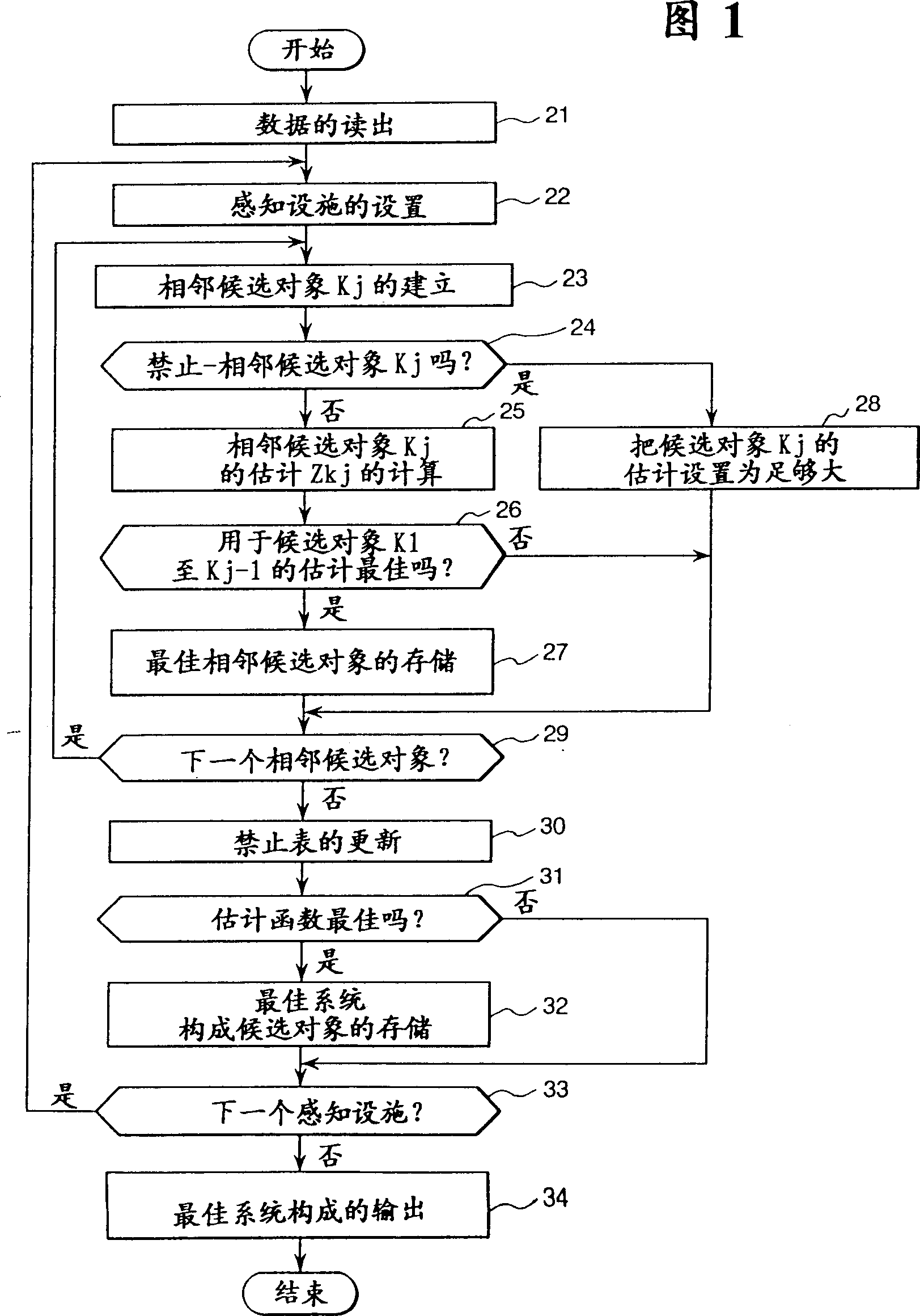
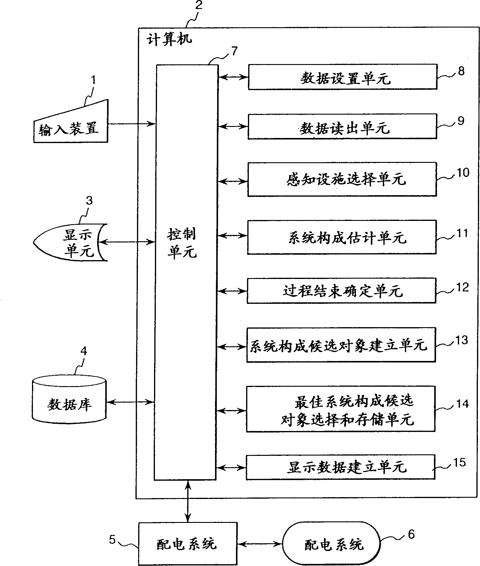
[0023] Fig. 1 is a flowchart showing an embodiment of the method for establishing a power network configuration of the present invention, the flowchart consists of figure 2 The network configuration establishment device of the illustrated embodiment of the present invention executes. Such as figure 2 As shown, the network configuration building apparatus includes an input device 1 , a computer 2 , a display unit 3 , and a database 4 . A power distribution system 6 is connected to the computer 2 via a power distribution system 5 .

[0024] As the input device 1, an input device such as a keyboard, mouse, or pointing device is suitably used. The computer 2 includes a control unit 7, a data setting unit 8, a data readout unit 9, a sensing switch selection unit 10, a network configuration estimation unit 11, a process end determination unit 12, a network configuration candidat...


PUM


Abstract

One of a plurality of switches constituting a power system is set as a perceived switch, and n optional switches Bk (k=1 to n) in the on state among the other switches are changed to the off state, and n loop networks including the perceived switch are created, and each switch Ck (k=1 to n) constituting the loop networks is changed from the off state to the on state so as to create a plurality of network configuration candidates, and a power network configuration is decided on the basis of the plurality of network configuration candidates.

Description

technical field [0001] The present invention relates to a method and equipment for establishing a power system network configuration, and more specifically, relates to a technique for determining the connection status of a power transmission and transformation facility system in a power distribution or transmission system. Background technique [0002] As a method of establishing a power system configuration, "power distribution system utilizing a genetic algorithm" as described in Journal of Institute of Electrical Engineers of Japan Vol. C116, No. 5 is considered Configuration Optimization Method" (PP.591 to598), for the limitation of feeder capacity, it is proposed to use native algorithm to determine the network configuration. According to this method, in order to maintain the radial network, the genetic structure of the native algorithm is made appropriate, and when setting a closed loop system or a distribution system due to exchange or replacement, preventive measures...

Claims


Application Information

Patent Timeline
IPC IPC(8): H02J3/00
CPCY04S10/545Y02E60/76Y02E40/76H02J3/00Y04S40/22H02J2003/007H02J2203/20Y02E40/70Y02E60/00Y04S10/50Y04S40/20
Inventor 泽敏之古川俊行大西司
Owner HITACHI LTD
Why Eureka
Try Eureka