
Blower

A blower and fan technology, applied in the direction of mechanical equipment, engine manufacturing, machine/engine, etc., can solve the problems of reduced air supply performance, excessive noise, loss, etc., to improve air volume performance, improve air volume performance and noise performance, and improve The effect of noise performance

Pending Publication Date: 2022-08-05
LG ELECTRONICS INC
View PDF7 Cites 0 Cited by
  • Summary
  • Abstract
  • Description
  • Claims
  • Application Information

AI Technical Summary

Problems solved by technology

[0005] However, the conventional fan unit cannot form the air sucked in from the lower part into a uniform upward airflow, so there is a problem that the purified air cannot be uniformly supplied to the discharge area extending vertically and long.
[0006] In addition, in the process of forming an updraft, there is a problem that the air blowing performance is reduced due to friction with the internal structure of the blower and flow separation, and excessive noise is generated.
[0007] In Korean Patent No. 10-2058859, a diagonal flow fan installed in an air conditioner is disclosed. However, there is a problem that the upper and lower lengths of the discharge area are limited due to the lack of a way to use the diagonal flow fan to form an upward airflow.
[0008] In Korean Granted Patent No. 10-1331487, a fan assembly using the Coanda effect to spit air forward is disclosed, however, due to the absence of a structure for suppressing eddy current generation and flow stripping during the formation of an updraft, there is excessive generation. noise problem

Method used


Image

  • Blower
  • Blower
  • Blower

Examples


Embodiment Construction

[0080] The advantages and features of the present invention and a method for realizing them will become more apparent by referring to the accompanying drawings and the embodiments described in detail later. However, the present invention is not limited to the embodiments disclosed below, but can be implemented in various forms. This embodiment is only for the purpose of more completely disclosing the present invention, so as to be more comprehensible to those skilled in the art to which the present invention belongs. The scope of the present invention is fully indicated, and the present invention is limited only by the scope of the claims. The same reference numerals denote the same structural elements throughout the specification.

[0081] Hereinafter, the present invention will be described with reference to the drawings for explaining the blower according to the embodiment of the present invention.

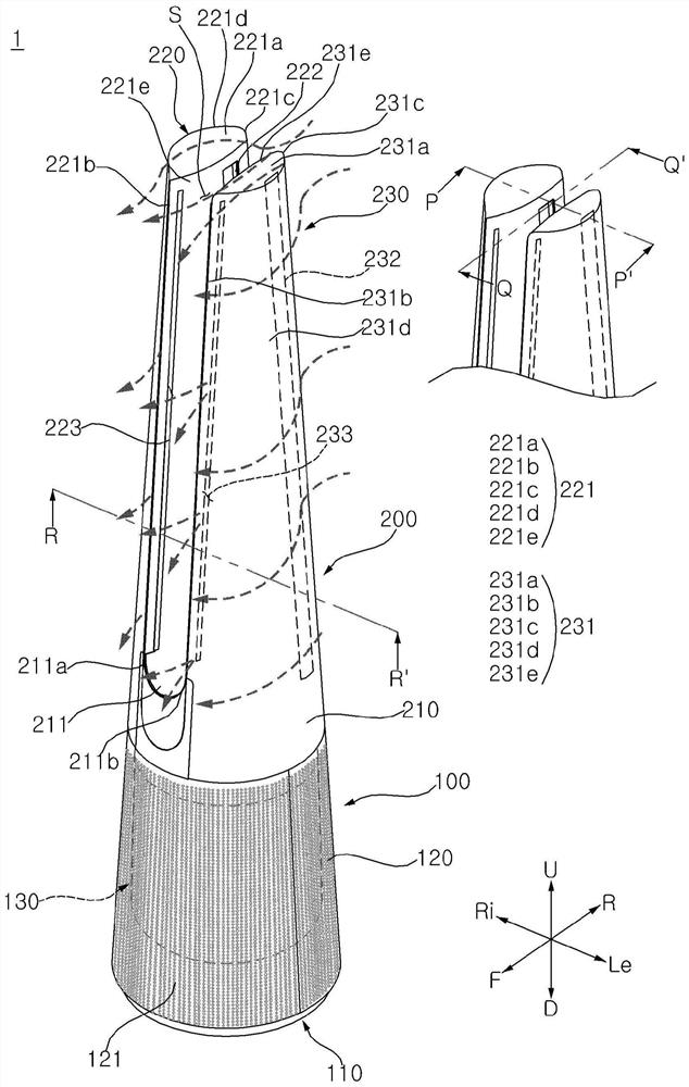
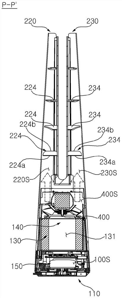
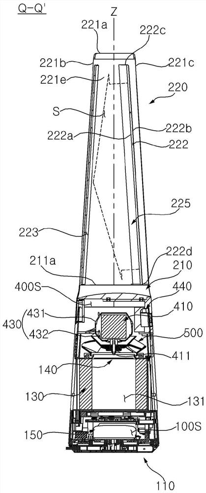
[0082] First, refer to figure 1 The overall structure of the blower 1 wi...


PUM


Abstract

The present invention relates to a blower, and the blower according to an embodiment of the present invention comprises: a lower case in which an intake hole into which air flows is formed; an upper housing disposed on the upper side of the lower housing and having a discharge port formed therein for discharging air; a fan disposed inside the lower case and having a plurality of blades, each of the plurality of blades including: a plurality of wings extending along mutually different mean camber lines; the front edge is connected with the front ends of the wing shapes, the inlet angles formed by the mean camber lines of the wing shapes and the rotating direction of the blades are different from one another, and the flow separated from the front edge can be reduced through the design of the bent shape of the front edge and the concave notches, so that the air volume performance can be improved.

Description

technical field [0001] The present invention relates to a blower, and more specifically, to a fan assembly arranged in the blower. Background technique [0002] The blower circulates the air in the indoor space or creates the airflow toward the user by generating the flow of the air. When the blower has a filter, the blower can improve the quality of indoor air by purifying the polluted air in the room. [0003] Inside the blower, a fan unit that sucks air and blows the sucked air to the outside of the blower is arranged. [0004] The area of ​​the air blown out from the blower extends long in the vertical direction to supply more purified air to the indoor space. [0005] However, since the conventional fan unit cannot form a uniform upward flow of the air sucked from the lower part, there is a problem that the purified air cannot be uniformly supplied to the discharge area extending long in the upper and lower directions. [0006] In addition, in the process of forming ...

Claims


Application Information

Patent Timeline
Patent Type & Authority Applications(China)
IPC IPC(8): F04D25/08F04D29/26F04D29/40F04D25/06F04D29/053F24F13/20F24F13/24
CPCF24F13/24F04D25/08F24F13/20F04F5/16F04D17/06F04D29/281F04D29/288F04D29/30F04D29/444F05D2250/52F05D2240/121F05D2240/303F04D29/681F24F2013/205F24F13/28F24F2013/247F04D29/053F04D29/4226F04D25/06F04D29/326F04D29/522
Inventor 郑裁赫崔硕浩李昌勋金柱贤朴亨镐金厚辰金容民崔致英
Owner LG ELECTRONICS INC
Learn More