
Electromagnetic field measuring device for outdoor power transmission line

A technology for transmission lines and measuring devices, applied in the direction of electromagnetic field characteristics, etc., can solve the problem of low accuracy of electromagnetic field, and achieve the effect of improving accuracy

Active Publication Date: 2022-08-05
CHENGDU AERONAUTIC POLYTECHNIC
View PDF11 Cites 0 Cited by
  • Summary
  • Abstract
  • Description
  • Claims
  • Application Information

AI Technical Summary

Problems solved by technology

[0005] The invention provides an outdoor transmission line electromagnetic field measuring device, which is used to solve the technical problem that the accuracy of the magnetic field sensor measuring the outdoor transmission line electromagnetic field in the prior art is not high

Method used


Image

  • Electromagnetic field measuring device for outdoor power transmission line
  • Electromagnetic field measuring device for outdoor power transmission line
  • Electromagnetic field measuring device for outdoor power transmission line

Examples


Embodiment 1

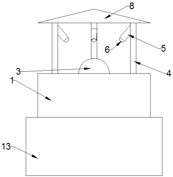
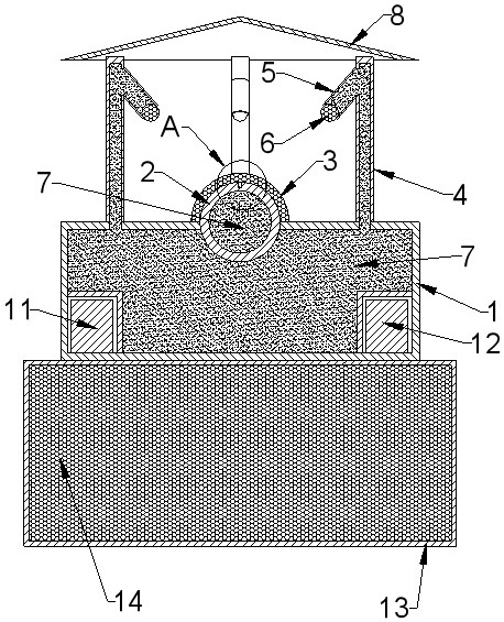
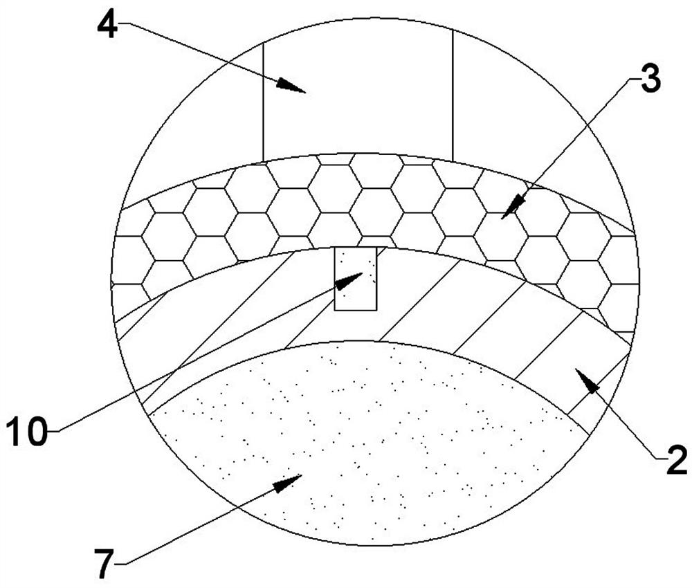
[0037] The electromagnetic field measurement device for outdoor transmission lines provided by the present invention includes a base 1, a hollow sphere 2, a deformation layer 3, a pipe body 4 and a pinhole camera 6, wherein:

[0038] like figure 1 and figure 2 As shown in the figure, a cavity is formed by hollowing out the interior of the above-mentioned base 1, a circular hole communicating with the above-mentioned cavity is opened at the central position of the top surface of the base 1, and the diameter of the above-mentioned hollow ball 2 is adapted to the diameter of the above-mentioned circular hole. The hollow ball 2 is fixed in the above-mentioned round hole by glue. At this time, the above-mentioned hollow ball 2 blocks the above-mentioned round hole, so that the cavity of the above-mentioned base 1 is a closed chamber. Half of the hollow sphere 2 is located outside the base 1 , and the hollow sphere 2 located outside the base 1 forms a hemispherical protrusion.

...

Embodiment 2

[0048] This embodiment is an improved implementation of Embodiment 1. Most of the electromagnetic field measurement device for outdoor transmission lines provided in this embodiment and the electromagnetic field measurement device for outdoor transmission lines provided in Embodiment 1 are the same but a few parts are different. The difference lies in :

[0049] like figure 1 and figure 2 As shown, the electromagnetic field measuring device for outdoor transmission lines provided in this embodiment further includes a sunshade canopy 8 , and the ends of the three above-mentioned pipes 4 facing away from the base 1 are all connected to the above-mentioned sunshade canopy 8 . Specifically, the sunshade canopy 8 is a conical shell structure, and one end of the pipe body 4 facing away from the base 1 is bolted and fixed to the sunshade canopy 8 . When the number of the pipe body 4 is one, the sunshade canopy 8 is bolted on the pipe body 4 .

[0050] Since the electromagnetic fi...

Embodiment 3

[0053] This embodiment is an improved implementation of Embodiment 1. Most of the electromagnetic field measurement device for outdoor transmission lines provided in this embodiment and the electromagnetic field measurement device for outdoor transmission lines provided in Embodiment 1 are the same but a few parts are different. The difference lies in :

[0054] like Figure 5 As shown, a sticker film 9 is adhered on the top surface of the base 1, the sticker film 9 is black, and the sticker film 9 surrounds the hemispherical protrusions. Since the pinhole camera 6 captures the image of the deformation layer 3, it not only captures the deformation layer 3, but also the top surface of the base 1, and the deformation layer 3 is usually not black. Therefore, with the help of the film, and If the film is black, the image of the deformation layer 3 captured by the pinhole camera 6 can be more easily distinguished from the top surface of the base 1 , so that the deformation amount ...


PUM


Abstract

The invention relates to an outdoor power transmission line electromagnetic field measuring device, and belongs to the technical field of magnetic field measurement. The device comprises a base, the interior of the base is hollowed to form a cavity, and a round hole communicated with the cavity is formed in the center of the top face of the base; the hollow ball is bonded and fixed in the round hole through glue, half of the hollow ball is located outside the base, and the hollow ball located outside the base forms a hemispherical protrusion; the deformation layer is made of magnetostrictive materials, and the deformation layer wraps the hemispherical protrusions; the pipe body is connected to the top face of the base and is perpendicular to the top face of the base, the pipe body is communicated with the cavity in the base, the end, away from the base, of the pipe body is sealed, a protruding pipe is fixedly arranged on the side wall of the pipe body, and the protruding pipe is communicated with the pipe body; the pinhole camera is mounted at a pipe opening of the convex pipe and blocks the convex pipe, and the pinhole camera faces the deformation layer; and phase change gel is arranged in the hollow ball, the convex tube, the tube body and the cavity of the base. Through the above structure, the device can measure the magnetic field intensity of the power transmission line more accurately.

Description

technical field [0001] The invention belongs to the technical field of magnetic field measurement, and in particular relates to an electromagnetic field measurement device for outdoor transmission lines. Background technique [0002] When the transmission line transmits electricity, a special and invisible magnetic field, that is, the electromagnetic field, will also be generated around the transmission line. Accurately measuring the electromagnetic field generated by the transmission line is not only a guarantee for the safety of line maintenance personnel, but also to understand whether the current and voltage transmitted in the transmission line are compliant. [0003] At present, the magnetic field strength around the transmission line is mainly measured by the magnetic field sensor. Most of such magnetic field sensors in the prior art are designed based on electromagnetic induction. With the help of the magnetic field around the transmission line, a weak current is gene...

Claims


Application Information

Patent Timeline
Patent Type & Authority Applications(China)
IPC IPC(8): G01R29/08
CPCG01R29/0871G01R29/0892
Inventor 龚雪郑丽
Owner CHENGDU AERONAUTIC POLYTECHNIC
Learn More