
Laser marking system

A laser marking and device box technology, applied in laser welding equipment, auxiliary welding equipment, welding equipment and other directions, can solve the problems of high and low temperature workpiece deformation, difficult to discharge, and reduce the quality of the workpiece, to improve quality, prevent offset printing, The effect of reducing the slight deformation

Inactive Publication Date: 2022-07-26
谢立涛
View PDF0 Cites 0 Cited by
  • Summary
  • Abstract
  • Description
  • Claims
  • Application Information

AI Technical Summary

Problems solved by technology

[0003] In the process of gasification marking of metal or plastic, some materials on the workpiece are gasified by the marking, so that some material particles are diffused in the air. Because the gasified particles are small, they are easily inhaled directly into the human body. , and it is difficult to discharge, especially for some metal particles, if they accumulate in the human body for a long time, it will cause serious health effects on the human body of the staff. Secondly, when marking some thin workpieces, due to the marking Printing is local high-temperature marking, so the difference between high and low temperature will cause local deformation of the workpiece, which will reduce the quality of the workpiece. Therefore, based on the above problems, an innovative design of the device is carried out

Method used


Image

  • Laser marking system
  • Laser marking system
  • Laser marking system

Examples


Embodiment Construction

[0028] In order to make it easy to understand the technical means, creation features, achieved goals and effects of the present invention, the present invention will be further described below with reference to the specific embodiments.

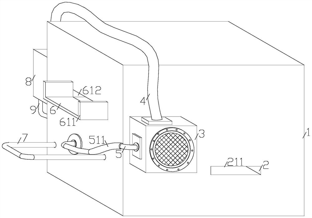
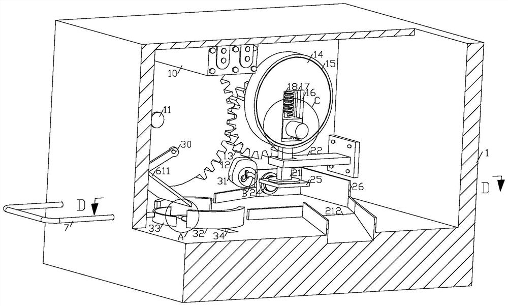
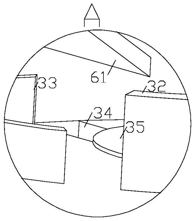
[0029] like Figure 1-Figure 7As shown in the figure, a laser marking system according to the present invention includes a device box 1, a fan 3 is fixedly installed on the front side of the device box 1, and a sealing box 8 is fixedly installed on the rear side of the device box 1, and a first fan 3 is fixedly installed on the left side of the fan 3 Two air pipes 5, a filter pipe 511 is fixed on the second air pipe 5, and the other end of the second air pipe 5 is connected to the left side of the device box 1, and the first air pipe 4 is fixedly installed on the upper end of the fan 3, and the first The other end of the gas transmission pipe 4 is connected to the upper side of the airtight box 8, and a wind wheel 29 is rotatably installed in...


PUM


Abstract

The invention relates to the field of laser marking, in particular to a laser marking system which comprises a device box, a draught fan is fixedly installed on the front side of the device box, a sealing box is fixedly installed on the rear side of the device box, a second gas conveying pipe is fixedly installed on the left side of the draught fan, and the other end of the second gas conveying pipe is connected to the left side of the device box in a penetrating mode. A first air conveying pipe is fixedly installed at the upper end of the fan, the other end of the first air conveying pipe is connected to the upper side of the sealing box in a penetrating mode, a wind wheel is rotatably installed in the sealing box, and a first connecting shaft is fixedly connected to the circle center position of the front side of the wind wheel; a marking machine is fixedly installed on the upper side of the interior of the device box on the front side of the driving gear, the other end of the first connecting shaft is fixedly installed at the circle center position of the driving gear, and the non-circle-center position of the front side end face of the driving gear is rotationally connected with a first rotating rod; the gas diffusion of the gasified material after marking can be reduced, and the deformation of the workpiece is reduced.

Description

technical field [0001] The invention relates to the field of laser marking, in particular to a laser marking system. Background technique [0002] Laser marking is a marking method that uses a high-energy-density laser to locally irradiate the workpiece to vaporize or change the color of the surface material, thereby leaving a permanent mark. Laser marking can print various characters, symbols and patterns, etc., which is of special significance to the anti-counterfeiting of products. [0003] In the process of vaporizing and marking metal or plastic, some materials on the workpiece are vaporized by the marking, so that some material particles are diffused in the air. Because the vaporized particles are small, they are easy to be directly inhaled into the human body. , and it is difficult to discharge, especially for some metal particles, the accumulation of metal particles in the human body for a long time will cause serious health effects on the human body of the staff. S...

Claims


Application Information

Patent Timeline
Patent Type & Authority Applications(China)
IPC IPC(8): B23K26/362B23K26/14B23K26/142B23K26/70B23K37/04
CPCB23K26/362B23K26/14B23K26/142B23K26/702B23K37/04B23K2101/007
Inventor 不公告发明人
Owner 谢立涛
Learn More