
Closed internal mold suitable for small box girder

A closed, small box girder technology, applied in the direction of ceramic molding core, ceramic molding mandrel, etc., can solve the problem that the formwork cannot be demoulded at the same time, and achieve the effect of saving labor hours, ensuring the appearance and internal quality, and simple construction

Pending Publication Date: 2022-08-05
湖南五新智能科技股份有限公司
View PDF0 Cites 0 Cited by
  • Summary
  • Abstract
  • Description
  • Claims
  • Application Information

AI Technical Summary

Problems solved by technology

[0009] The invention provides a closed inner mold suitable for small box girders with simple structure, convenient installation and disassembly, economical and practical, large operating space in the inner cavity, and simple construction, which solves the need for manual plastering and templates on both sides of the inner mold in the prior art. The problem of not being able to unmold at the same time

Method used


Image

  • Closed internal mold suitable for small box girder
  • Closed internal mold suitable for small box girder
  • Closed internal mold suitable for small box girder

Examples


Embodiment 1

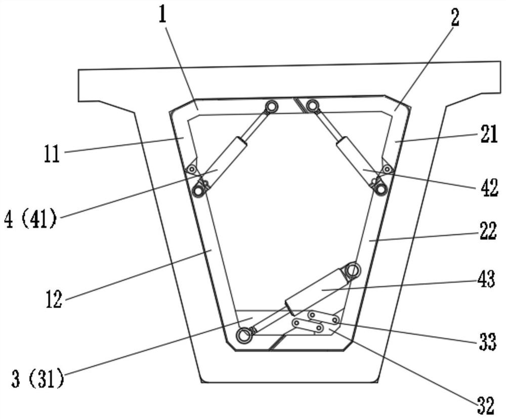
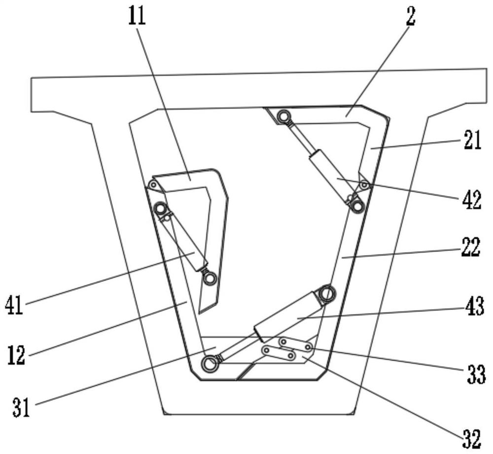
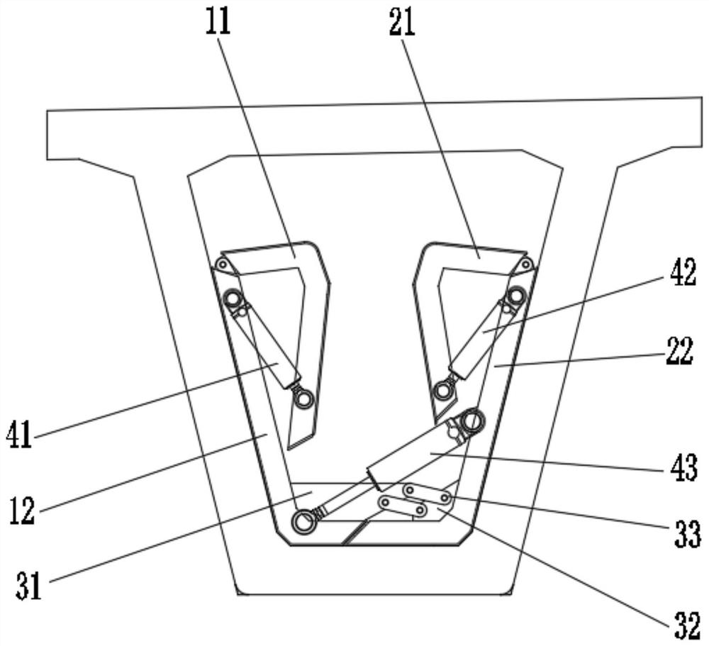
[0035] like Figure 1 to Figure 4 As shown, the present invention is suitable for a closed inner mold of a box girder with a smaller cross-sectional size, including a first side mold assembly 1 , a second side mold assembly 2 , a trajectory control mechanism 3 and a telescopic assembly 4 . The trajectory control mechanism 3 is used to connect the first side mold assembly 1 and the second side mold assembly 2 into a whole, and can make them close or open in relative translation along the set trajectory. Multiple sets of telescopic assemblies 4 are respectively arranged on the upper and lower parts of the first side mold assembly 1 and the second side mold assembly 2, and the telescopic assemblies 4 are used to drive the first side mold assembly 1 and the second side mold assembly 2. When opening and closing, the inner mold forms a closed inner mold shape when it is opened, and the whole section is smaller than the beam end outlet when it is contracted and closed. It should be ...

Embodiment 2

[0052] like Figure 5 As shown in the figure, the present invention is suitable for a closed inner mold of a box girder with a smaller cross-sectional size, and has a similar structure to that of the inner mold in Example 1. The main difference is that the second side lower mold 22 includes a side mold 221. And the bottom mold 222, the side mold 221 and the bottom mold 222 can perform relative movement. Further, the side molds 221 and the bottom mold 222 can be hinged or attached by bevel, and the bottom mold 222 and the second side lower mold 12 can be beveled. It can be understood that in other embodiments, the upper and lower molds of the first side mold assembly 1 and the upper and lower molds of the second side mold assembly 2 can be further split into a plurality of mutually connected templates, so that the inner mold after the mold is closed. The mold has a smaller volume and also provides a larger operating space for the small box girder cavity.

[0053] like Figur...


PUM


Abstract

The invention discloses a closed inner mold suitable for a small box girder. The closed inner mold comprises a first side mold assembly, a second side mold assembly, a track control mechanism and a telescopic assembly. The track control mechanism is used for connecting the first side mold assembly and the second side mold assembly into a whole and can enable the first side mold assembly and the second side mold assembly to be oppositely closed or opened along a set track. The telescopic assembly is used for driving the first side mold assembly and the second side mold assembly to define a closed inner mold shape when being unfolded, and the whole section is smaller than a beam end outlet when the inner mold is contracted and folded. The device has the advantages of being stable in structure, large in inner cavity operation space, easy to construct, economical, practical and the like, the problem that in the prior art, a formwork cannot be installed in a partial area of an inner formwork of a small box girder is solved, the problem that manual pouring and plastering are needed after demolding is further solved, and the construction efficiency of the box girder is remarkably improved.

Description

technical field [0001] The invention belongs to the technical field of bridge box girder inner moulds, and particularly relates to a closed inner mould suitable for small box beams. Background technique [0002] The inside of the box girder is a hollow cavity. During the prefabrication of the box girder, the inner mold needs to be embedded inside, and the mold is released after the concrete is poured. The end outlet of the beam body is smaller than the inner cavity section of the beam, and the template needs to undergo a large shrinkage before it can be demolded. [0003] In the prior art, the formwork is assembled and formed in a single segment. The two top formwork is pulled by two vertical oil cylinders to pull the top and bottom formwork to be demolded. Sliding seat, after demoulding, lift the template and remove the template through the sliding seat. The scheme has the following problems: [0004] 1. Due to the existence of the sliding seat, the template cannot be fu...

Claims


Application Information

Patent Timeline
Patent Type & Authority Applications(China)
IPC IPC(8): B28B7/30
CPCB28B7/30
Inventor 王薪程夏仙桃谢亮
Owner 湖南五新智能科技股份有限公司
Learn More