High-temperature sewage closed cooling and white smoke eliminating equipment with waste heat recovery function
A high-temperature sewage and waste heat recovery technology, which is applied in heat recovery systems, lighting and heating equipment, adsorption water/sewage treatment, etc., can solve the problems of slow cooling speed, slow heat conduction speed, and waste of high-temperature sewage, so as to improve cooling speed, Improve heat exchange efficiency and eliminate white pollution
- Summary
- Abstract
- Description
- Claims
- Application Information
AI Technical Summary
Problems solved by technology
Method used
Image
Examples
Embodiment 1
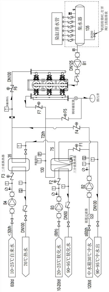
[0033] A high-temperature sewage closed cooling and whitening equipment with waste heat recovery, such as figure 1 As shown, it includes a drain pipe, a water collector, a sewage pump, a steel ball filter unit, a primary heat exchanger, a secondary heat exchanger and a sewage well; In the water collector, the water collector has the characteristics of heat preservation to prevent temperature loss and carrying high pressure. The water collector is equipped with a pressure sensor to effectively monitor the internal pressure and provide a start signal for the sewage pump, which pumps the high-temperature sewage in the water collector. It is filtered in a recyclable steel ball filter unit, and the filtered sewage enters one side of the primary heat exchanger through the pipeline for primary heat exchange work. Cooling water and high-temperature sewage conduct first-stage heat exchange. One end of the first-stage heat exchanger is fed with softened water of 10°C-25°C on the opposit...
Embodiment 2
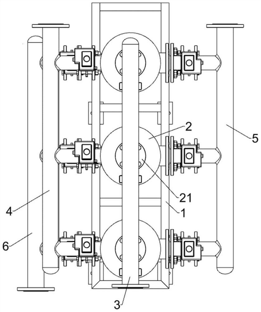
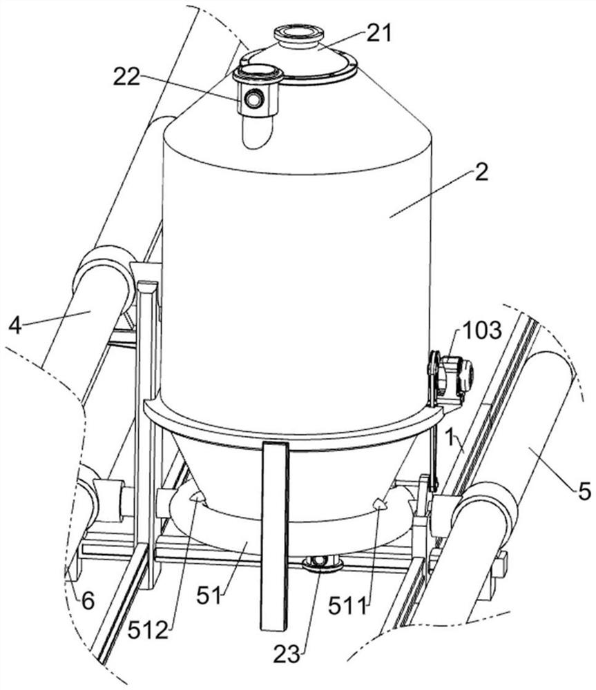
[0036] This embodiment is further optimized on the basis of Embodiment 1, such as Figure 2-Figure 9 As shown, the steel ball filter unit includes a mounting bracket 1, a filter cabin 2, an infusion pipe 3, a liquid inlet pipe 4, a liquid outlet pipe 5, an annular pipe 51, a sewage pipe 6, a filter cartridge 7, a filter steel ball, and a middle isolation plate. 9 and conical plug 10; several filter cabins 2 are connected with bolts on the mounting bracket 1; the infusion pipe 3 is flanged between the liquid inlet valves 21 of the filter cabin 2; the water pump flange is connected to the liquid inlet of the infusion pipe 3; The liquid inlet pipe 4 is installed on the upper part of the left side of the installation bracket 1; the left side of all the filter cabins 2 are connected to the liquid inlet pipe 4 through the pipe flange, and the filter screen 24 is installed on the left outlet of the filter cabin 2; the right side of the installation bracket 1 is installed. A liquid ou...
PUM
 Abstract
Description
Claims
Application Information
 - R&D
- Intellectual Property
- Life Sciences
- Materials
- Tech Scout
- Unparalleled Data Quality
- Higher Quality Content
- 60% Fewer Hallucinations
Browse by: Latest US Patents, China's latest patents, Technical Efficacy Thesaurus, Application Domain, Technology Topic, Popular Technical Reports.
© 2025 PatSnap. All rights reserved.Legal|Privacy policy|Modern Slavery Act Transparency Statement|Sitemap|About US| Contact US: help@patsnap.com


