
Rapid switching type superconducting current-limiting transformer and working method thereof

A technology of fast switching and superconducting current limiting, applied in the usage of superconducting elements, emergency protection circuit devices for limiting overcurrent/overvoltage, and protection against overcurrent, to improve current limiting depth and limit The effect of large flow characteristics, volume and weight reduction

Pending Publication Date: 2022-08-02
XI AN JIAOTONG UNIV
View PDF2 Cites 0 Cited by
  • Summary
  • Abstract
  • Description
  • Claims
  • Application Information

AI Technical Summary

Problems solved by technology

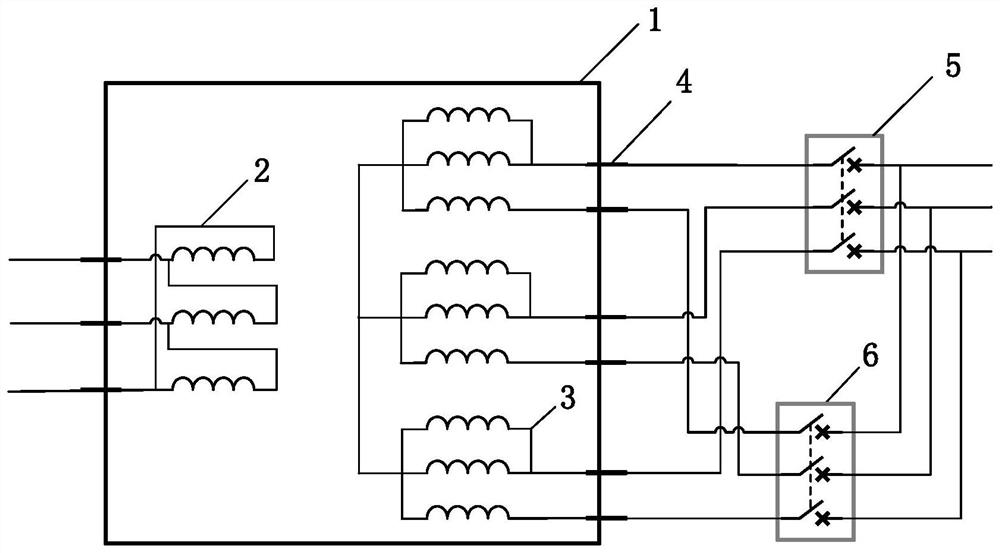
[0005] Aiming at the fact that existing superconducting transformers and superconducting current-limiting transformers cannot well realize fault current-limiting functions, the present invention proposes a fast-switching superconducting current-limiting transformer and its working method. The present invention utilizes different connection modes and In the action state, change the topological structure and current-limiting impedance of the superconducting transformer winding, realize the variable impedance current-limiting function, and realize the breaking of the remaining short-circuit current after current-limiting through another fast switch outside the Dewar, and clear the fault of the superconducting current-limiting transformer

Method used


Image

  • Rapid switching type superconducting current-limiting transformer and working method thereof
  • Rapid switching type superconducting current-limiting transformer and working method thereof
  • Rapid switching type superconducting current-limiting transformer and working method thereof

Examples


Embodiment Construction

[0031] The present invention will be further described in detail below with reference to the accompanying drawings and specific embodiments.

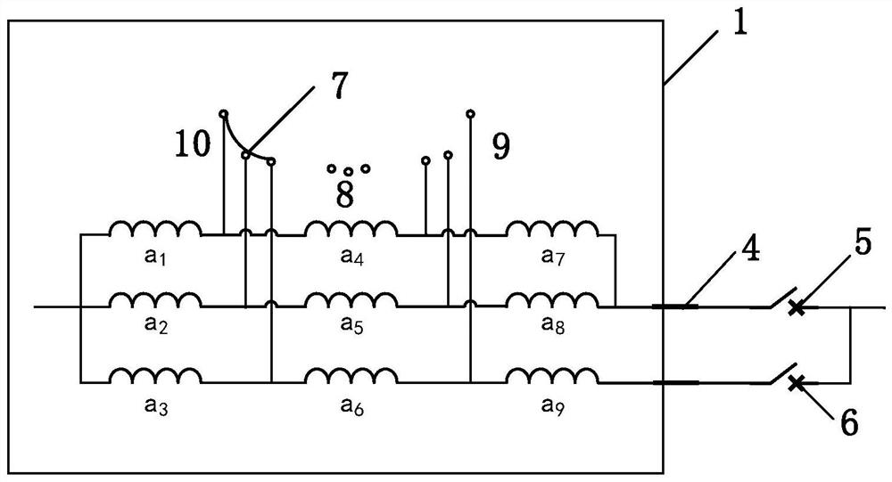
[0032] like figure 1As shown in the figure, a fast-switching superconducting current-limiting transformer of the present invention includes a low-temperature dewar 1, a high-voltage winding 2, a low-voltage winding 3, and lead-out terminals of the superconducting winding (two lead-out terminals 9 and 10 in this embodiment), The first fast switch 5, the second fast switch 6 and the third fast switch 7; the low-voltage winding 3 is a superconducting winding, and the high-voltage winding 2 and the low-voltage winding 3 are immersed in the cooling liquid in the low-temperature Dewar 1 and lead out through the lead-out tap 4; Each phase of the low-voltage winding 3 is divided into two parts: the main current-passing winding and the main current-limiting winding. The main current-passing winding is connected in series with the first fast swit...


PUM


Abstract

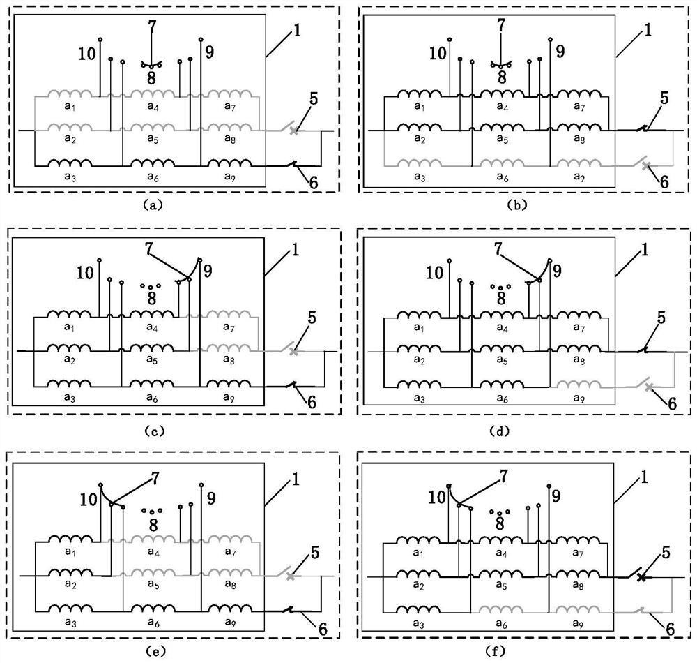
The invention discloses a high-speed switch type superconducting current-limiting transformer and a working method thereof. The superconducting current-limiting transformer comprises a low-temperature Dewar, a high-voltage winding, a low-voltage winding, a leading-out terminal of a superconducting winding, a first high-speed switch, a second high-speed switch and a third high-speed switch, the high-voltage winding and the low-voltage winding are soaked in the cooling liquid in the low-temperature Dewar flask and are led out through the lead-out taps; each phase of the low-voltage winding is divided into a main through-flow winding and a main current-limiting winding, the main through-flow winding is connected in series with a first high-speed switch through a leading-out tap, the main current-limiting winding is connected in series with a second high-speed switch through a leading-out tap, and the main through-flow winding and a branch where the main current-limiting winding is located are connected in parallel; the low-voltage winding is provided with a group of mutually insulated leading-out terminals at intervals; and the third quick switch is arranged in an upper gas area of the Dewar and is connected with a leading-out terminal or a neutral gear of the low-voltage winding. Under a short-circuit fault, the length of the superconducting tape cut off when the first quick switch is switched off is changed through the action of the third quick switch, the current-limiting impedance of the superconducting winding is increased, and variable-impedance current limiting is realized.

Description

technical field [0001] The invention relates to the technical fields of superconducting technology, transformer technology and switching appliances, in particular to a superconducting transformer device that uses fast switching to change the winding topology of a superconducting transformer to realize voltage transformation and multi-topology variable impedance current limiting. Background technique [0002] With the continuous development of the economy, the demand for electricity continues to increase, the scale of the power grid is also increasing, the requirements for transmission capacity are also increasing, and the short-circuit current will continue to increase, jeopardizing the security of the system. Superconducting transformers and superconducting current-limiting transformers are based on the zero-resistance characteristics of the superconducting state of superconducting materials and the resistance characteristics of quench time, combined with the current capacit...

Claims


Application Information

Patent Timeline
Patent Type & Authority Applications(China)
IPC IPC(8): H02H9/02H02H3/02H02H3/08
CPCH02H9/023H02H3/025H02H3/08Y02E40/60
Inventor 项彬张琦李思熠李宏旭王东宇王建华耿英三
Owner XI AN JIAOTONG UNIV
Learn More