
Extreme weather efficient protection structure for power equipment

A technology for extreme weather and power equipment, applied in the field of high-efficiency protection structures for extreme weather for power equipment, it can solve problems such as power paralysis, damage to distribution boxes, collapse of distribution boxes, etc., and achieve the effect of promoting snow removal and protecting power equipment.

Pending Publication Date: 2022-08-02
苟小刚
View PDF0 Cites 0 Cited by
  • Summary
  • Abstract
  • Description
  • Claims
  • Application Information

AI Technical Summary

Problems solved by technology

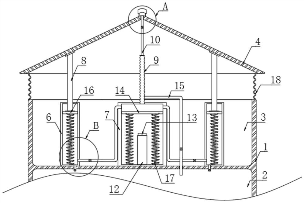
[0003] For some of the current outdoor distribution boxes, especially in some areas prone to extreme weather, there will be hail damage to the distribution box, and snow will collapse the distribution box, which will cause power failure in extreme weather. paralyzed situation, so we need to consider designing an efficient protection structure for power equipment with extreme weather

Method used


Image

  • Extreme weather efficient protection structure for power equipment
  • Extreme weather efficient protection structure for power equipment
  • Extreme weather efficient protection structure for power equipment

Examples


Embodiment 1

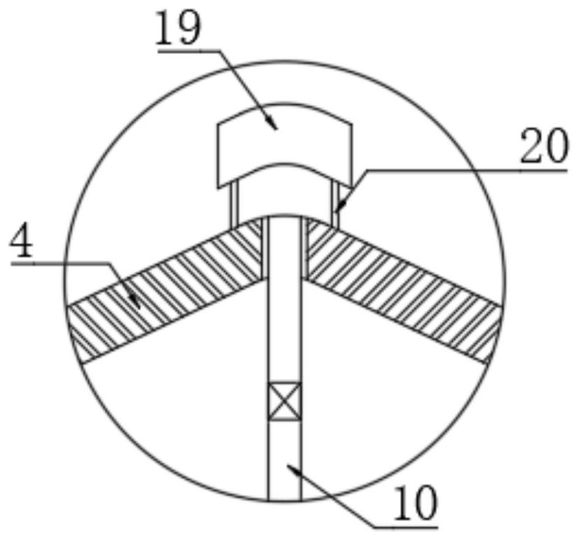
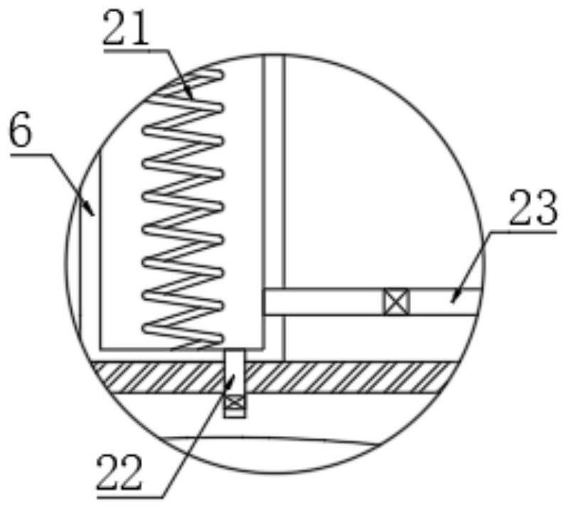
[0024] refer to Figure 1-3 , an extreme weather and high-efficiency protection structure for power equipment, comprising a casing 1, a rectangular cavity 2 is arranged in the casing 1, and a rectangular groove 3 is opened at the upper end of the casing 1;

[0025] As an embodiment of the present invention, in order to reduce the damage to electric equipment caused by rainstorm or hail, a protection module is provided above the casing 1 , and the protection module includes a top cover 4 arranged on the upper end of the casing 1 , and the lower end of the top cover 4 is connected to the upper part of the casing 1 . An annular folding bag 18 is arranged between the upper ends of the casing 1. The upper end surface of the top cover 4 is composed of two relatively symmetrical inclined surfaces. The top cover 4 is composed of two inclined plates at the upper end and two triangular plates on the front and rear sides. Two first rectangular boxes 6 are symmetrically arranged at the in...

Embodiment 2

[0035] refer to Figure 4-5 The difference between this embodiment and Embodiment 1 is that the rectangular cavity 2 is filled with a solution of snow melting agent, and the bottom space of the telescopic tube 9 is communicated with the bottom space of the rectangular groove 3 through the second communication pipe 24. The second communication pipe 24 A second solenoid valve 25 and a one-way valve are installed inside. The one-way valve ensures that the snow melting agent in the rectangular cavity 2 enters the telescopic tube 9 in one direction, and a check valve is installed at the lower end of the telescopic tube 9 to avoid backflow. In this case, the inner bottom of the first rectangular box 6 on the left side is fixedly connected with a second mounting block 5, the upper end of the second mounting block 5 is mounted with a second time-delay touch switch 11, and the first piston plate 16 is made of conductive material and Grounding the wire ensures that the second delay touc...


PUM


Abstract

The invention discloses an extreme weather efficient protection structure for power equipment, which comprises a shell, a rectangular cavity is formed in the shell, and a rectangular groove is formed in the upper end of the shell; a protection module is arranged above the shell, the protection module comprises a top cover arranged at the upper end of the shell, an annular folding bag is arranged between the lower end of the top cover and the upper end of the shell, the upper end face of the top cover is composed of two symmetrical inclined planes, two first rectangular boxes are symmetrically arranged at the inner bottom of a rectangular groove, and the first rectangular boxes are arranged in the rectangular groove. And a first piston plate capable of sliding up and down is arranged in each first rectangular box. The protection structure can effectively protect the power equipment in some extreme weathers, so that the influence of the extreme weathers on the power equipment is reduced, heat dissipation can be carried out on the interior of the power equipment in the protection process, and the situation that heat in the equipment is gathered due to the fact that the power load in the extreme weathers is large is avoided.

Description

technical field [0001] The invention relates to the field of power equipment protection, in particular to an extreme weather high-efficiency protection structure for power equipment. Background technique [0002] The distribution box is an electrical equipment with the characteristics of small size, easy installation, special technical performance, fixed location, etc. It is widely used, stable and reliable in operation, and is used for power distribution; [0003] For some outdoor distribution boxes now, especially in some areas prone to extreme weather, there will be hail damage to the distribution box, and snow will crush the distribution box, which will cause electricity in extreme weather. In the case of paralysis, we need to consider the design of an efficient protective structure for power equipment with extreme weather. SUMMARY OF THE INVENTION [0004] The purpose of the present invention is to solve the shortcomings in the prior art, and proposes a high-efficien...

Claims


Application Information

Patent Timeline
Patent Type & Authority Applications(China)
IPC IPC(8): H02B1/56H02B1/28H02B1/46H02B1/48
CPCH02B1/565H02B1/28H02B1/46H02B1/48Y02A30/14
Inventor 苟小刚
Owner 苟小刚
Learn More