
Optical element, optical module and beam shaping method

A technology of optical components and optical modules, which is applied in the field of optics, can solve the problems of high production cost, high requirements for installation and alignment accuracy, uneven spot, etc., and achieve high degree of freedom, diverse beam forms, and high flexibility Effect

Pending Publication Date: 2022-08-02
FOCUSLIGHT TECH
View PDF1 Cites 0 Cited by
  • Summary
  • Abstract
  • Description
  • Claims
  • Application Information

AI Technical Summary

Problems solved by technology

[0003] Due to the large divergence angle of semiconductor lasers, the beam superposition at the center position is stronger than that at the edge position, resulting in a Gaussian distribution of output spot energy and uneven spot
In order to solve the unevenness of the spot caused by the large divergence angle, at present, the flat-top spot can be realized by dividing the beam and superimposing it one by one. However, this method needs to control the parameters of each differential unit one by one, which requires high structural accuracy. The production cost is relatively high, and the accuracy of assembly and adjustment is relatively high.

Method used


Image

  • Optical element, optical module and beam shaping method
  • Optical element, optical module and beam shaping method
  • Optical element, optical module and beam shaping method

Examples


Embodiment Construction

[0079] The embodiments set forth below represent the necessary information to enable those skilled in the art to practice the embodiments, and illustrate the best mode for practicing the embodiments. After reading the following description with reference to the accompanying drawings, those skilled in the art will appreciate the concepts of the present disclosure and will recognize applications of these concepts not specifically set forth herein. It should be understood that these concepts and applications are within the scope of the present disclosure and appended claims.

[0080] It will be understood that, although the terms first, second, etc. may be used herein to describe various elements, these elements should not be limited by these terms. These terms are only used to distinguish one element from another. For example, a first element could be termed a second element, and, similarly, a second element could be termed a first element, without departing from the scope of t...


PUM


Abstract

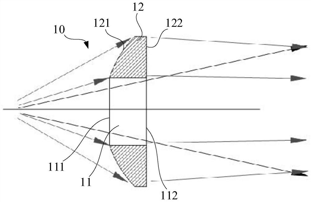
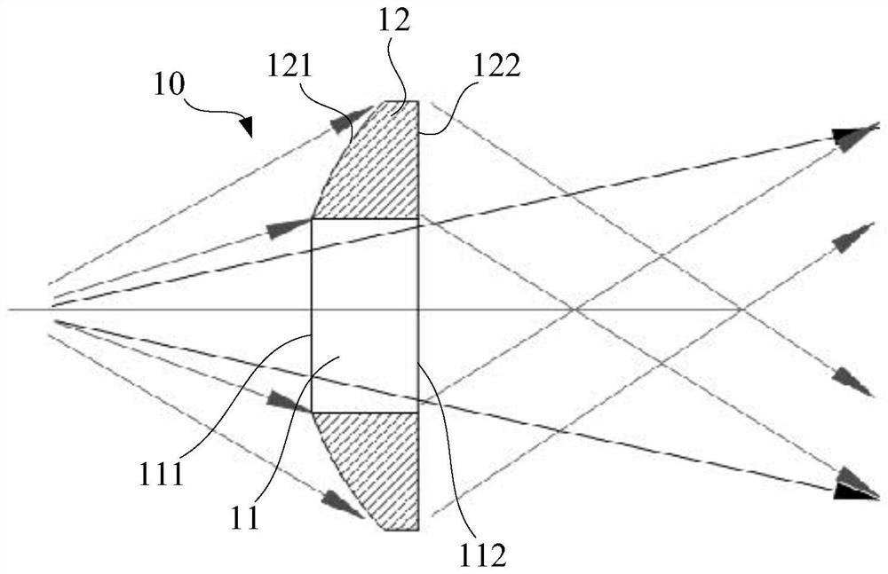
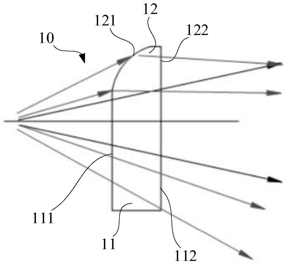
An optical element, an optical module and a light beam shaping method relate to the technical field of optics, the optical element comprises a transmission part and a refraction part, the refraction part surrounds the transmission part, the transmission part comprises a transmission incident surface and a transmission emergent surface, the refraction part comprises a refraction incident surface and a refraction emergent surface, incident light enters the transmission incident surface and the refraction incident surface, and the transmission incident surface and the refraction emergent surface are opposite to each other. The light beam is refracted by the refracting part and then is emitted by the refracting emergent surface to form a refracted light beam with second energy distribution, and the transmitted light beam and the refracted light beam are superposed to form a light beam with third energy distribution. The optical element can cut and rearrange the light beams, so that the distribution characteristics of the light beams are changed, and the optical element is suitable for different application scenes.

Description

technical field [0001] The present invention relates to the field of optical technology, and in particular, to an optical element, an optical module and a beam shaping method. Background technique [0002] Semiconductor lasers have the advantages of small size, light weight, high reliability, long service life and low power consumption. They have been widely used in various fields of the national economy, such as pumping, medical treatment and industrial processing. However, the current promotion and application of semiconductor lasers will be restricted by their beam quality. Therefore, improving the output spot uniformity, brightness and power of semiconductor lasers has become an important research direction. [0003] Due to the large divergence angle of the semiconductor laser, the superposition of the beam at the center position is stronger than that at the edge position, resulting in a Gaussian distribution of the output spot energy and uneven spot. In order to solve ...

Claims


Application Information

Patent Timeline
Patent Type & Authority Applications(China)
IPC IPC(8): G02B27/09
CPCG02B27/0938G02B27/095G02B27/0955G02B27/0961
Inventor 蔡磊刘兴胜
Owner FOCUSLIGHT TECH
Learn More