
Method and system for monitoring hydrogen leakage amount of stator cooling water of generator

A generator and cold water technology, applied in the direction of water testing, nuclear power generation, greenhouse gas reduction, etc., can solve the problems that cannot be completely eliminated, cannot be monitored in real time and accurately, and cannot be protected from gas removal, etc., to achieve simple composition, The effect of small measurement error and easy maintenance

Pending Publication Date: 2022-08-02
刘忠
View PDF6 Cites 0 Cited by
  • Summary
  • Abstract
  • Description
  • Claims
  • Application Information

AI Technical Summary

Problems solved by technology

This technology mainly uses the measuring device of hydrogen concentration and gas flow, which belongs to the gas monitoring technology. Its working principle is that the hydrogen leaked into the fixed cooling water tank of the generator is monitored after it escapes from the water in a section of the gas layer above the water tank, not only It is related to the thickness of the gas layer in this section, and is also related to factors such as water level changes in the water tank, water temperature, and protective gas. In addition, the gas-liquid separator 4 cannot remove the protective gas (including water vapor cannot be completely removed), so this method cannot be real-time. and accurately monitor the hydrogen leakage in the fixed cooling water of the generator

Method used


Image

  • Method and system for monitoring hydrogen leakage amount of stator cooling water of generator
  • Method and system for monitoring hydrogen leakage amount of stator cooling water of generator
  • Method and system for monitoring hydrogen leakage amount of stator cooling water of generator

Examples


Embodiment 1

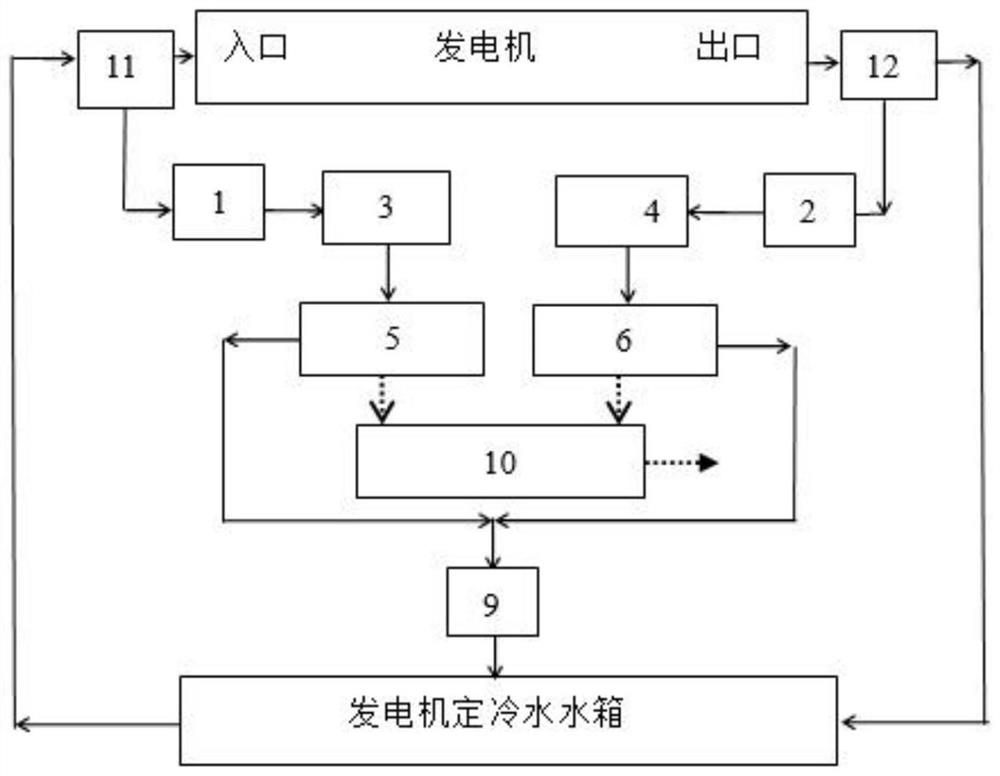
[0046] see figure 1 It is a system of the present invention for directly monitoring the amount of hydrogen leakage of cold water from a generator. The solid line in the figure represents the connection of the water flow pipeline, and the dotted line represents the signal connection. The system includes: fixed cold water inlet water sampling point 11, generator fixed cold water outlet water sample 12, inlet water sampling valve 1, outlet water sampling valve 2, fixed cold water inlet water sample cooler 3, fixed cold water outlet water sample cooler 4, paired An online dissolved hydrogen sensor 5 for monitoring the water sample at the inlet of the fixed cold water, an online dissolved hydrogen sensor 6 for monitoring the water sample at the outlet of the fixed cold water, a confluence funnel 9, and a calculation module 10 for the hydrogen leakage of the fixed cold water. The fixed cold water tank provides cooling circulating water for the generator stator.

[0047] The fixed c...

Embodiment 2

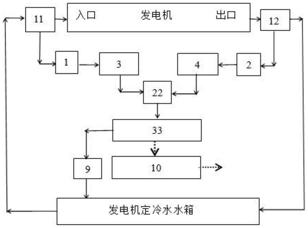
[0058] see figure 2 Embodiment 2 of the present invention is a system for directly monitoring the amount of hydrogen leakage of cold water from a generator. The solid line in the figure represents the connection of the water flow pipeline, and the dotted line represents the signal connection. The difference between Example 2 and Example 1 is that the number of on-line dissolved hydrogen sensors provided is different. In this embodiment, there is only one online dissolved hydrogen sensor 33 and one three-way valve 22 . as the picture shows:

[0059] The fixed cold water inlet water sampling point 11 is connected with the inlet end of the inlet water sampling valve 1 through a pipeline, and the outlet end of the inlet water sampling valve 1 is connected with the inlet of the fixed cold water inlet water sample cooler 3 through a pipeline. The outlet is connected to one end of the three-way valve 22 through a pipeline. The generator constant cold water inlet water sample 12 i...

Embodiment 3

[0063] see image 3 Embodiment 3 of the present invention is a system for directly monitoring the amount of hydrogen leakage of cold water from a generator. The solid line in the figure represents the connection of the water flow pipeline, and the dashed line represents the signal connection. The difference between Embodiment 3 and Embodiment 2 is that the number of three-way valves 22 is two. A three-way valve 22 is respectively provided at the outlet of the constant cold water inlet water sample cooler 3 and the constant cold water outlet water sample cooler 4, and the same on-line dissolved hydrogen sensor 33 is connected through the three-way valve 22. One end of the two three-way valves 22 is also directly or indirectly connected to the generator cooling water tank or the waste water discharge system. The on-line dissolved hydrogen sensor 33 is signally connected to the calculation module 10 for determining the amount of hydrogen leakage of the cooling water. When the o...


PUM


Abstract

The invention relates to a method for monitoring the hydrogen leakage amount in generator stator cooling water in real time, and the method comprises the following steps: S1, at a certain moment t0, collecting an inlet water sample at a generator stator cooling water inlet, cooling the water sample, and measuring the dissolved hydrogen concentration A in cooling water; s2, at the moment of t0 + t delta, collecting an outlet water sample at a stator cooling water outlet of the generator, cooling the water sample, and measuring the concentration B of dissolved hydrogen in cooling water; the t delta is equal to 0 to 10s; and S3, calculating the hydrogen leakage amount in the stator cooling water of the generator according to the difference value between the B and the A. The method provided by the invention directly monitors the water samples at the inlet and outlet of the stator cooling water in real time, has the characteristics of high sensitivity and high reaction speed, can capture tiny hydrogen leakage conditions in time, and greatly improves the monitoring level of the operation safety of the generator. In addition, the invention further provides a system adaptive to the method, the system is simple in composition, the hydrogen leakage amount in stator cooling water of the generator can be automatically monitored in real time by setting a calculation program and a valve control program, and the system is simple in composition and easy to maintain.

Description

technical field [0001] The invention relates to a monitoring technology for a generator cooling water system, in particular to a method and a system for monitoring the hydrogen leakage in the generator cooling water in real time. Background technique [0002] The stator winding cooling water system is also called the stator cooling water system or the stator water system. The company's generator stator windings are directly cooled by cooling water, which will greatly reduce the temperature of the hottest spot and reduce the temperature difference between adjacent components that may cause thermal expansion, thereby reducing the mechanical stress on each component to minimum. During the normal operation of the generator, due to the vibration and aging of the equipment, it is difficult to avoid the problem of hydrogen leakage or increase of leakage points in the cooling water of the generator, which leads to an increase in the operation risk of the generator. In the cooling ...

Claims


Application Information

Patent Timeline
Patent Type & Authority Applications(China)
IPC IPC(8): G01N33/18
CPCG01N33/18Y02E30/30
Inventor 刘忠
Owner 刘忠
Learn More