Angle steel clamp with automatic lubricating function
A technology of automatic lubrication and angle steel, which is applied in the direction of clamping, manufacturing tools, metal processing machinery parts, etc., can solve the problems of incomplete clamping, lack of anti-skid structure, lack of protective structure, etc.
- Summary
- Abstract
- Description
- Claims
- Application Information
AI Technical Summary
Problems solved by technology
Method used
Image

Examples
Embodiment 2
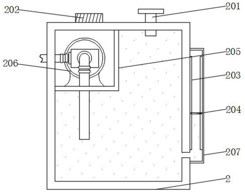
[0043] Example 2: see figure 2 , Figure 5 and Image 6 , an embodiment provided by the present invention: an angle steel clamp with automatic lubrication function, a box cover 201 is installed on the top of the lubrication box 2, a buzzer 202 is installed on the top of the lubrication box 2, and the inner top wall of the lubrication box 2 is installed A waterproof box 205 is installed, a lubrication pump 206 is installed on the inner bottom wall of the waterproof box 205, a water inlet pipe is installed at the input end of the lubrication pump 206, and one end of the water inlet pipe extends into the interior of the lubrication box 2, and the output end of the lubrication pump 206 is installed There is a lubricating pipe, and one end of the lubricating pipe extends out of the outer wall of the lubrication box 2, the outer wall of the lubrication box 2 is provided with an observation groove 207, the inner wall of the observation groove 207 is provided with a lifting groove 2...
Embodiment 3
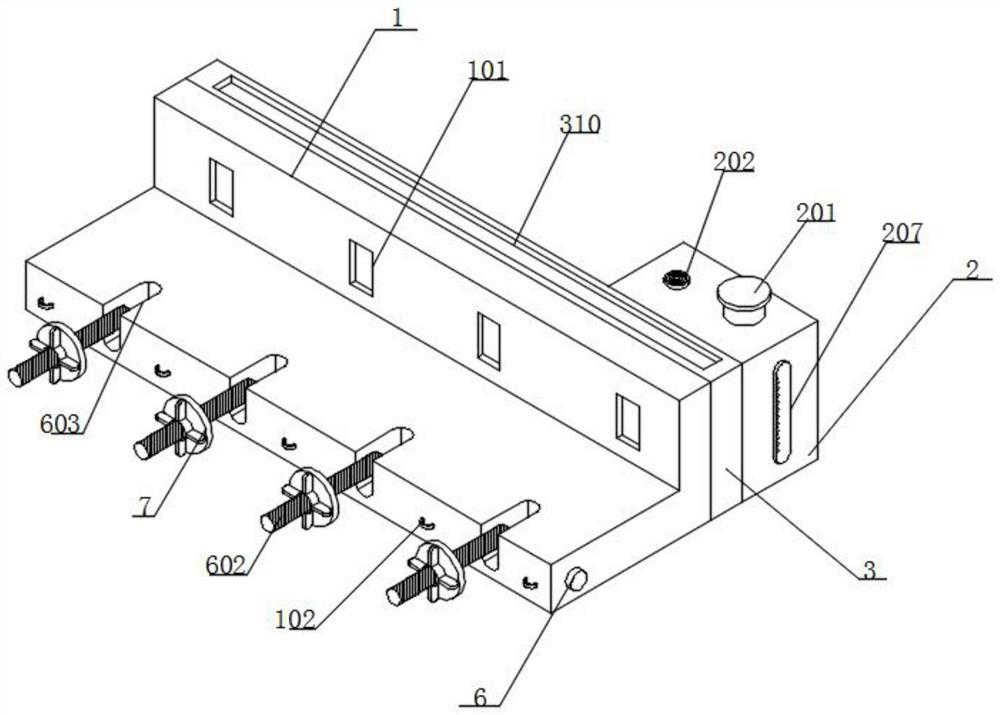
[0044] Example 3: see figure 1 , Image 6 and Figure 7 , an embodiment provided by the present invention: an angle steel clamp with automatic lubrication function, the top of the splint 1 is provided with a plurality of slots 603, and one end of the roller 6 penetrates the outer wall of the slot 603, and the outer wall of the roller 6 A bearing 601 is installed, a threaded post 602 is installed on the outer wall of the bearing 601, a clamping disc 7 is sleeved on the outer wall of the threaded post 602, a handle 8 is installed on the front of the outer wall of the clamping disc 7, and bolts 701 are installed through the outer wall of the clamping disc 7 , a connecting rod 702 is installed on the inner top wall of the clamping plate 7, a second spring 703 is installed on the outer wall of the connecting rod 702, an anti-skid plate 705 is installed on the bottom of the connecting rod 702, and a plurality of anti-skid columns 706 are installed on the bottom of the anti-skid pla...
Embodiment 4
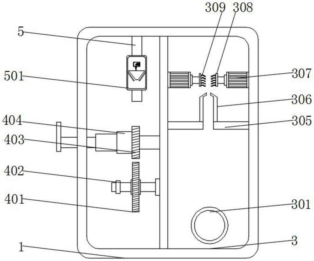
[0045] Example 4: see image 3 and Figure 4 , an embodiment provided by the present invention: an angle steel clamp with automatic lubrication function, the inner wall of the splint 1 is installed with a transmission shaft, the outer wall of the transmission shaft is installed with a drive gear 401, and the outer wall of the transmission shaft is installed with a sprocket 402, and The sprocket 402 is connected with the output end of the No. 1 motor 4 through a chain drive. A fixed shaft is installed on the inner wall of the splint 1, a driven wheel 403 is installed on one end of the fixed shaft, and an electric telescopic rod 404 is installed on the outer wall of the driven wheel 403. One end of the rod 404 extends out of the front of the clamping groove 101, one end of the electric telescopic rod 404 is installed with a clamping plate, the front of the clamping plate 1 is provided with a plurality of clamping grooves 101, and the front of the clamping plate 1 is installed wi...
PUM
 Abstract
Description
Claims
Application Information
 - Generate Ideas
- Intellectual Property
- Life Sciences
- Materials
- Tech Scout
- Unparalleled Data Quality
- Higher Quality Content
- 60% Fewer Hallucinations
Browse by: Latest US Patents, China's latest patents, Technical Efficacy Thesaurus, Application Domain, Technology Topic, Popular Technical Reports.
© 2025 PatSnap. All rights reserved.Legal|Privacy policy|Modern Slavery Act Transparency Statement|Sitemap|About US| Contact US: help@patsnap.com