Roof steel net rack for building

A technology for steel grids and buildings, which is applied to buildings, building components, building structures, etc., can solve problems such as height difference, inability to adjust distances, waste of time, etc., to avoid deformation, connect securely, and reduce distance changes. Effect

Active Publication Date: 2022-07-29
徐州宇隆重型科技有限公司
View PDF11 Cites 2 Cited by
  • Summary
  • Abstract
  • Description
  • Claims
  • Application Information

AI Technical Summary

Problems solved by technology

[0003] The main purpose of the present invention is to provide a steel grid frame for building roofs, which can effectively solve the problem that it takes a lot of time to align the fixing grooves and fixing steps before welding between the support columns and the fixing frame in the background technology, which is a waste of time. , so that the progress of erecting the house is relatively slow, and there is a certain height difference between the fixing frame and the supporting column below, so that the fixing frame and the supporting column need to add a connecting device, so that the fixing frame and the supporting column are welded, which is troublesome , and when the distance between the two fixed frames is uncertain or changed, the position of the first fixed beam needs to be installed according to the distance, so the distance between the first fixed beams cannot be adjusted, and the roof iron sheet cannot be welded Finally, it is troublesome to weld the first fixed beam, and there is also the problem that the distance between the fixed frames or the fixed beams are prone to deformation, so that the steel structure is prone to cracks at the welding place

Method used


Image

  • Roof steel net rack for building
  • Roof steel net rack for building
  • Roof steel net rack for building

Examples


Embodiment 1

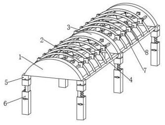
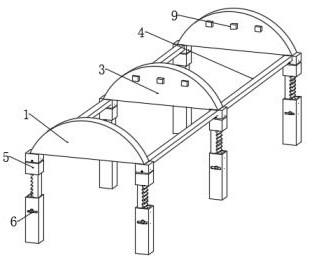
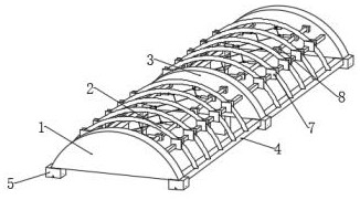
[0032] like Figure 1-8As shown, a roof steel grid frame for construction includes a first fixing frame 1, a first fixing beam 2, a second fixing frame 3 and a second fixing beam 4, and the second fixing beam 4 is arranged on the first fixing frame 1 and the second fixing beam 4. The first fixed beams 2 are welded between the second fixed frames 3 and between the second fixed beams 4. The two ends of the first fixed frame 1 and the second fixed frame 3 are provided with a compensation structure 5 and a lifting structure 6. The compensation structure 5 is connected with both ends of the first fixing frame 1, the lifting structure 6 is welded to the bottom end of the compensation structure 5, a first connecting block 9 is arranged between the first fixing frame 1 and the second fixing frame 3, and the first fixing frame 5 is A connecting structure 8 is provided between the frame 1 and the second fixing frame 3, and both ends of the connecting structure 8 are connected with the f...

Embodiment 2

[0034] like Figure 4-5 As shown, the compensation structure 5 includes a second connecting block 501, a first fixing groove 502, a compensation block 503, a first reserved groove 504, a first telescopic spring 505, a first connecting rod 506, a second connecting rod 507, a second The telescopic spring 508, the second fixing groove 509, the middle block 510, the second connecting block 501 is welded on both ends of the first fixing frame 1 and the second fixing frame 3, the middle block 510 is arranged inside the second connecting block 501, the middle The inside of the block 510 is provided with a first fixing slot 502, the top of the lifting structure 6 is provided with a compensation block 503, the compensation block 503 is arranged inside the first fixing slot 502, the second fixing slot 509 and the first reserved slot 504 are arranged in the compensation block 503. Inside the block 503 , the first connecting rod 506 is disposed inside the first reserved groove 504 , the f...

Embodiment 3

[0036] like Figure 4 and Image 6 As shown, the lifting structure 6 includes a third connecting block 601, a connecting bar 602, a clamping groove 603, a connecting column 604, a clamping column 605, a clamping bar 606, a third telescopic spring 607, a third connecting rod 608, a third The fixing slot 609 and the second reserved slot 610, the third connecting block 601 is connected with the connecting bar 602, the clamping slot 603 is arranged on the side wall of the connecting bar 602, the third fixing slot 609 is opened in the interior of the connecting column 604, and The connecting bar 602 is located inside the third fixing groove 609 of the connecting column 604, the second reserved groove 610 is opened on both sides of the connecting column 604, and the clamping column 605 is arranged inside the second reserved groove 610, and the clamping column 605 is welded with the clamping bar 606, the third connecting rod 608 is arranged inside the clamping bar 606, and the third...


PUM


Abstract

The invention discloses a building roof steel net rack which comprises a first fixing frame, first fixing beams, second fixing frames and second fixing beams, the second fixing beams are arranged between the first fixing frame and the second fixing frames, and the first fixing beams are welded between the second fixing beams. Compensation structures and lifting structures are arranged at the two ends of the first fixing frame and the two ends of the second fixing frame, and the compensation structures are connected with the two ends of the first fixing frame. The roof steel net rack for the building belongs to the technical field of buildings, errors of fixing frames and supporting columns can be compensated through compensation blocks and middle blocks, the height of a first fixing frame and a compensation structure can be adjusted, the supporting columns at the bottom end of a lifting structure are matched with the height of the fixing frames, and the distance between first fixing beams can be adjusted; the distance change between the first fixing frame and the second fixing frame can be reduced, and deformation of steel structures of the first fixing frame and the second fixing frame is avoided.

Description

technical field [0001] The invention relates to the technical field of construction, in particular to a roof steel mesh frame for construction. Background technique [0002] At present, prefabricated buildings refer to buildings assembled on site with prefabricated components. The advantages of this type of building are fast construction, less climatic conditions, and labor saving. The roof of the building is generally made of mesh steel. Welded and then erected the roof on a steel mesh frame. However, the existing roof steel mesh frame for construction has certain disadvantages. First, it takes a lot of time to align the fixing groove and the fixing step before welding between the support column and the fixing frame, which is a waste of time and makes the progress of building the house. It is relatively slow, and there is a certain height difference between the fixing frame and the supporting column below, so that the fixing frame and the supporting column need to be added...

Claims


Application Information

Patent Timeline
Patent Type & Authority Applications(China)
IPC IPC(8): E04B7/08E04B1/343E04C3/40
CPCE04B7/08E04B1/3431E04C3/40
Inventor 车德军
Owner 徐州宇隆重型科技有限公司
Why Eureka
Try Eureka