Driver fence with danger identification and alarm functions and identification method thereof
A driver and function technology, applied in the field of driver fence, can solve the problems of inability to carry out rapid warning and single function of driver fence, and achieve the effect of enriching functionality, improving use safety and improving safety.
- Summary
- Abstract
- Description
- Claims
- Application Information
AI Technical Summary
Problems solved by technology
Method used
Image
Examples
Embodiment 1
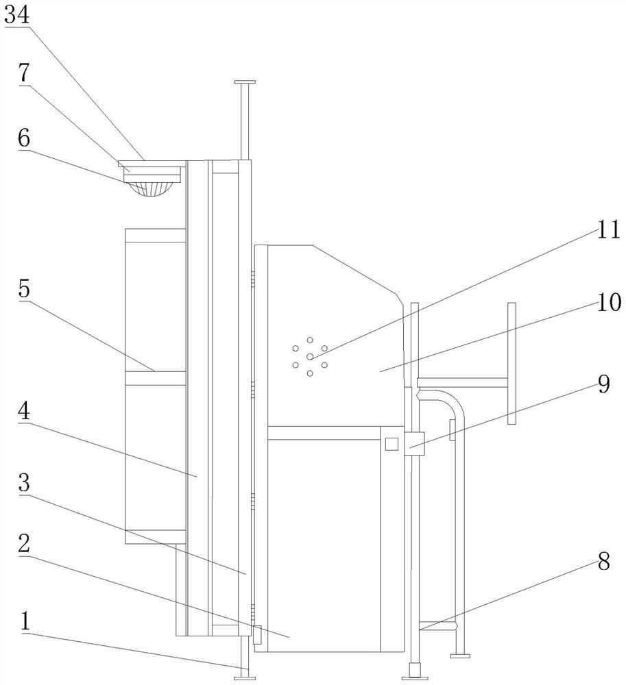
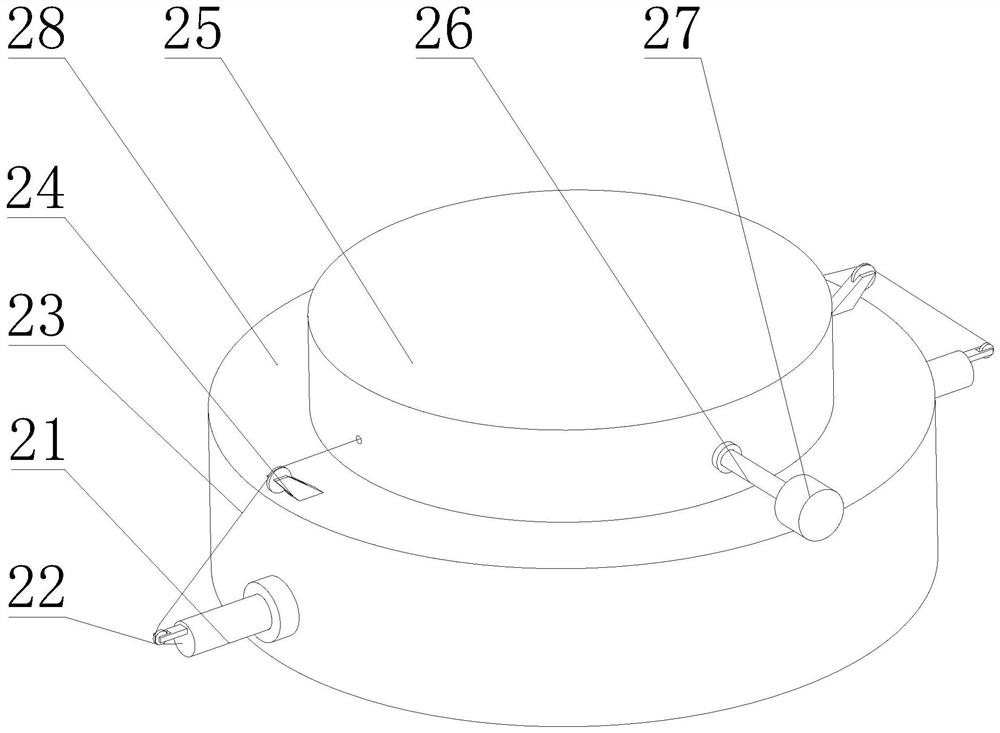
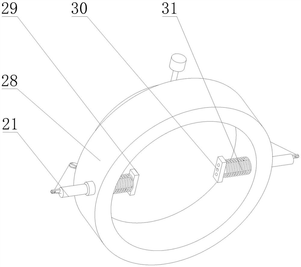
[0035] see Figures 1 to 4 , In the embodiment of the present invention, it includes a first pillar 1, a second pillar 8, an isolation door 2 and a rear partition 3, the first pillar 1 is fixedly installed between the top and bottom surfaces of the interior of the bus, and the second pillar 8 is fixedly installed On the top surface of the inside of the bus and parallel to the first pillar 1, the second pillar 8 is fixedly installed with an isolation door lock 9 for use with the isolation door 2, and the first pillar 1 is fixedly connected to the inner side of the bus. There is a rear partition 3, the rear partition 3 is located at the rear of the driver's working area, one side of the isolation door 2 is hinged with the first pillar 1, and the other side and the second pillar 8 are fixedly connected through the isolation door lock 9, and The isolation door 2 is located at the side of the driver's work area, and the rear partition 3 and the isolation door 2 form an isolation fo...
Embodiment 2
[0044] see figure 1 , Figure 5 and Image 6 On the basis of Embodiment 1, the interior of the isolation door lock head 9 is hollowed out, and one end of the isolation door lock head 9 close to the isolation door 2 is provided with a through groove, and the top surface and the bottom surface of the isolation door lock head 9 are close to the through groove. There are chutes 18 in all positions,
[0045] The isolation door lock head 9 is provided with a sliding plate 35, and the two ends of the sliding plate 35 are respectively slid in the two chutes 18, and a spring 17 is fixedly connected between the end of the sliding groove 18 away from the isolation door 2 and the sliding plate 35, and the sliding plate 35 One side close to the isolation door 2 is fixedly connected with the lock tongue 12, the other side of the slide plate 35 is fixedly installed with the magnetic block 13, and the lock tongue 12 is slidably connected with the through groove;
[0046] The isolation door...
Embodiment 3
[0050] see figure 2 and image 3 , On the basis of Embodiment 2, a mounting frame 5 is also fixedly connected to the side of the mounting plate 4 away from the rear partition 3 . Through the setting of the mounting frame 5, a promotional poster or an electronic display screen can be installed, which further improves the practicability of the driver's fence.
PUM
 Abstract
Description
Claims
Application Information
 - R&D Engineer
- R&D Manager
- IP Professional
- Industry Leading Data Capabilities
- Powerful AI technology
- Patent DNA Extraction
Browse by: Latest US Patents, China's latest patents, Technical Efficacy Thesaurus, Application Domain, Technology Topic, Popular Technical Reports.
© 2024 PatSnap. All rights reserved.Legal|Privacy policy|Modern Slavery Act Transparency Statement|Sitemap|About US| Contact US: help@patsnap.com


