


Quick Research
Generate reliable direction feasibility study reports for your R&D in just a few steps.

Technical Q&A
Discover and master advanced knowledge NOW. Basics, ideas, possibilities, all at once.

Find Solutions
As an expert in R&D theories, this can generate solutions to your technical problems instantly.

Evaluate Feasibility
Analyze your overall solution with one click, know your potential R&D risks in advance.

Monitor Landscape
Get weekly tech updates, stay abreast of the latest tech innovations and key insights.
Self-locking mechanism, end cover assembly, installation method of end cover assembly, water cutting part and automobile
An end cover assembly and self-locking technology, which is applied in the field of auto parts, can solve problems such as poor surface profile, external water shear deformation, and inapplicability, and achieve the effect of convenient and fast process, reduced installation force, and convenient installation
- Summary
- Abstract
- Description
- Claims
- Application Information
AI Technical Summary
Problems solved by technology
Method used
Image

Examples
Embodiment 1
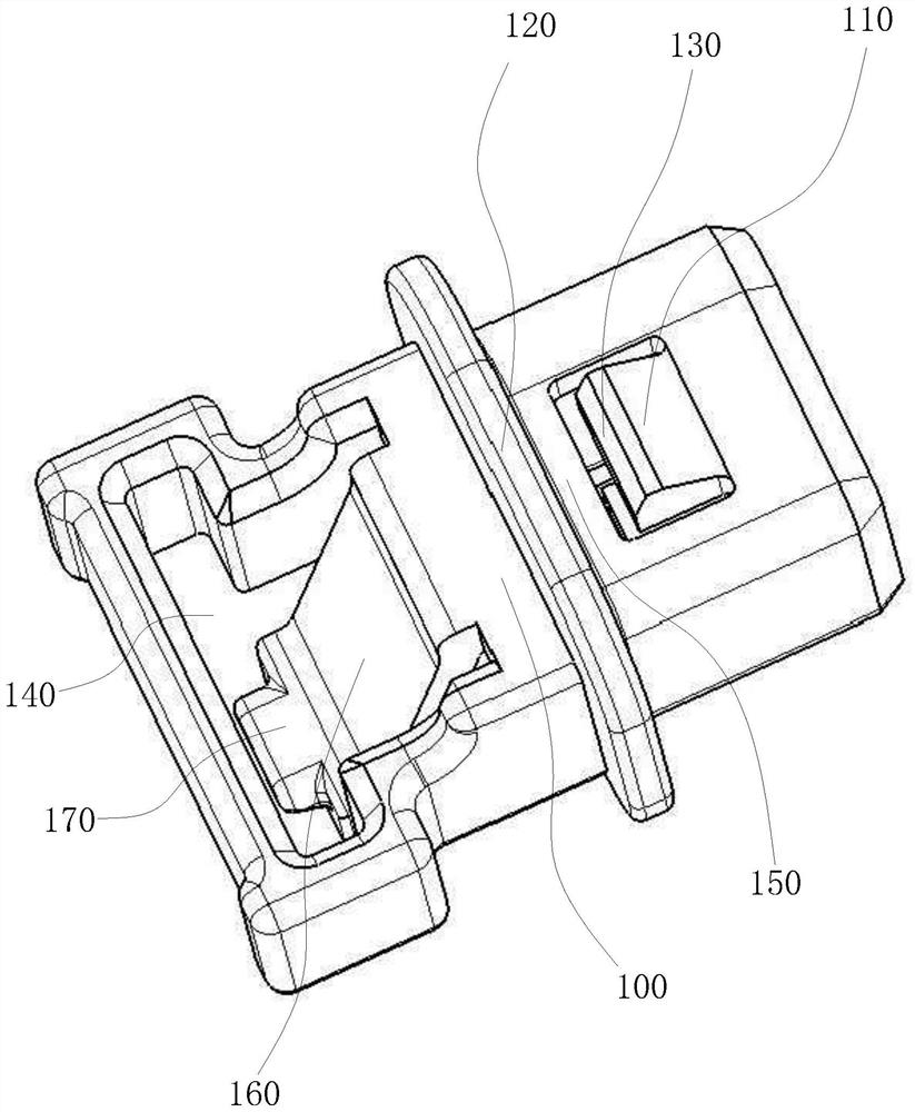
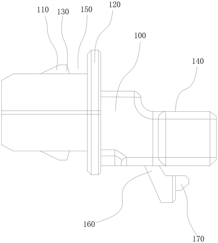
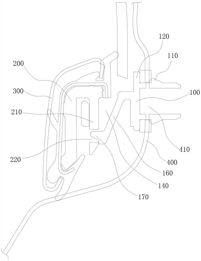
[0041] Example 1: as Figure 1-12 As shown, a self-locking mechanism is provided, the self-locking mechanism is used to cooperate with the end cap to allow the water cut to be installed on the automobile sheet metal 400 downward along the Z direction, including: a self-locking seat 100 along the self-locking seat 100 A spring piece 110, a first limit block 120 and a locking hole 140 are arranged in sequence in the length direction. One end of the spring piece 110 close to the first limit block 120 is tilted and a second limit block 130 is provided. A sheet metal locking portion 150 is formed between the limiting block 120 and the second limiting block 130 ; the self-locking seat 100 is further provided with an end cap locking unit ( Wherein, when the self-locking seat 100 is inserted into the sheet metal hole 410, the opening of the locking hole 140 is disposed upward.
[0042] Specifically, the self-locking seat 100 can be inserted into the sheet metal hole 410 along the len...
Embodiment approach
[0047] like Figure 1-10 As shown, the end cap locking unit only needs to be able to be locked together with the inserts 210 on the end cap. In the actual structure, the following embodiments may be preferred and not limited, for example:
[0048] In Embodiments 1-4, as figure 1 As shown, the end cap locking unit is set as the elastic cantilever 160, and is locked together with the insert 210 on the end cap through the hook 170. Preferably, the end cap locking unit is set as the elastic cantilever 160, and the elastic cantilever 160 is located obliquely in the locking hole 140 , one end of the elastic cantilever 160 is integrally connected with the self-locking seat 100 , and the other end of the elastic cantilever 160 is provided with a hook 170 .
[0049] The elastic cantilever 160 is arranged in an oblique shape, so when the insert 210 on the end cap is inserted into the locking hole 140 , the insert 210 can push the elastic cantilever 160 to deform. When the hook 170 is ...
Embodiment 2
[0054] Embodiment 2: as Figure 1-10 As shown, an end cap assembly is also provided, including: an end cap body 200 and a self-locking mechanism, the end cap body 200 is provided with an insert piece 210, the insert piece 210 is inserted into the locking hole 140 and locked with the end cap The unit is connected so that the end cap body 200 is fixedly connected with the self-locking seat 100 .
[0055] The end cap body 200 is fixed with the water cut, and the water cut is connected with the self-locking mechanism through the end cap body 200. When locking, the end cap body 200 is inserted into the self-locking seat 100 from top to bottom along the Z direction. During the locking process , the insert piece 210 of the end cap is inserted into the locking hole 140, and the insert piece 210 is connected with the hole wall of the locking hole 140 in a collision, thereby limiting the degrees of freedom of the insert piece 210 in the Y direction and the X direction, and the end cap l...
PUM
 Abstract
Description
Claims
Application Information
 - R&D Engineer
- R&D Manager
- IP Professional
- Industry Leading Data Capabilities
- Powerful AI technology
- Patent DNA Extraction
Browse by: Latest US Patents, China's latest patents, Technical Efficacy Thesaurus, Application Domain, Technology Topic, Popular Technical Reports.
© 2024 PatSnap. All rights reserved.Legal|Privacy policy|Modern Slavery Act Transparency Statement|Sitemap|About US| Contact US: help@patsnap.com