
Laser parallel processing equipment

A processing equipment, laser technology, applied in metal processing equipment, laser welding equipment, welding equipment and other directions, to achieve the effect of increasing suction, reducing escape distance, and improving dust removal efficiency

Active Publication Date: 2022-07-29
NANJING TRIZ INST OF LASER APPL TECH CO LTD
View PDF5 Cites 0 Cited by
  • Summary
  • Abstract
  • Description
  • Claims
  • Application Information

AI Technical Summary

Problems solved by technology

[0004] The object of the present invention is to provide a kind of laser parallel processing equipment, to solve the problem of prior art shortcoming in the above-mentioned background technology

Method used


Image

  • Laser parallel processing equipment
  • Laser parallel processing equipment
  • Laser parallel processing equipment

Examples


Embodiment Construction

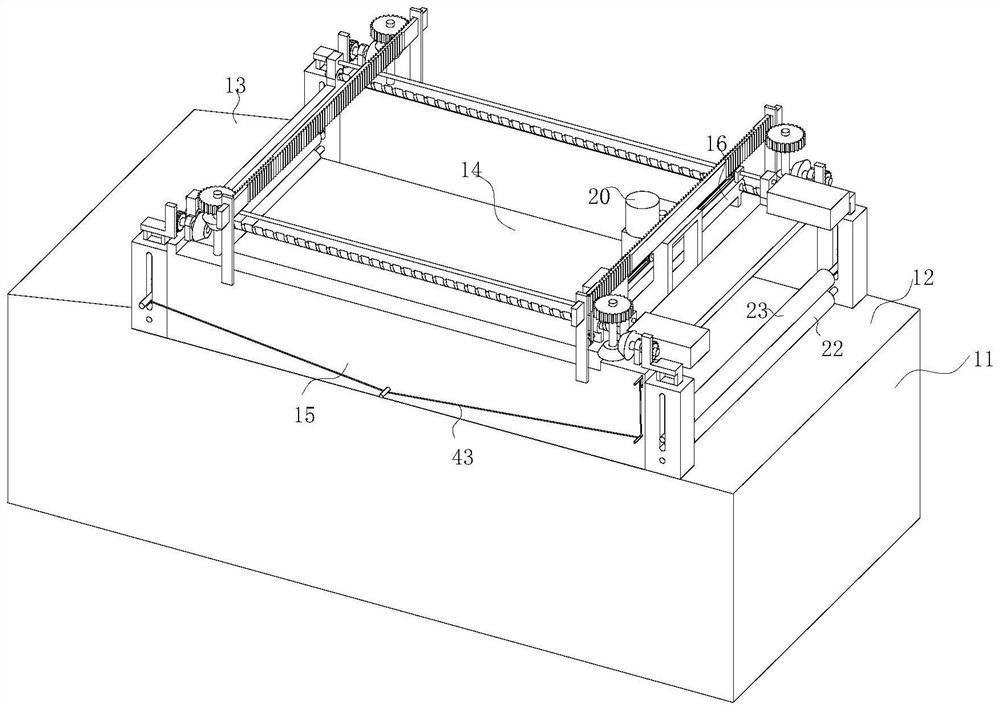
[0036]The technical solutions in the embodiments of the present invention will be clearly and completely described below with reference to the accompanying drawings in the embodiments of the present invention. Obviously, the described embodiments are only a part of the embodiments of the present invention, but not all of the embodiments. Based on the embodiments of the present invention, all other embodiments obtained by those of ordinary skill in the art without creative efforts shall fall within the protection scope of the present invention.

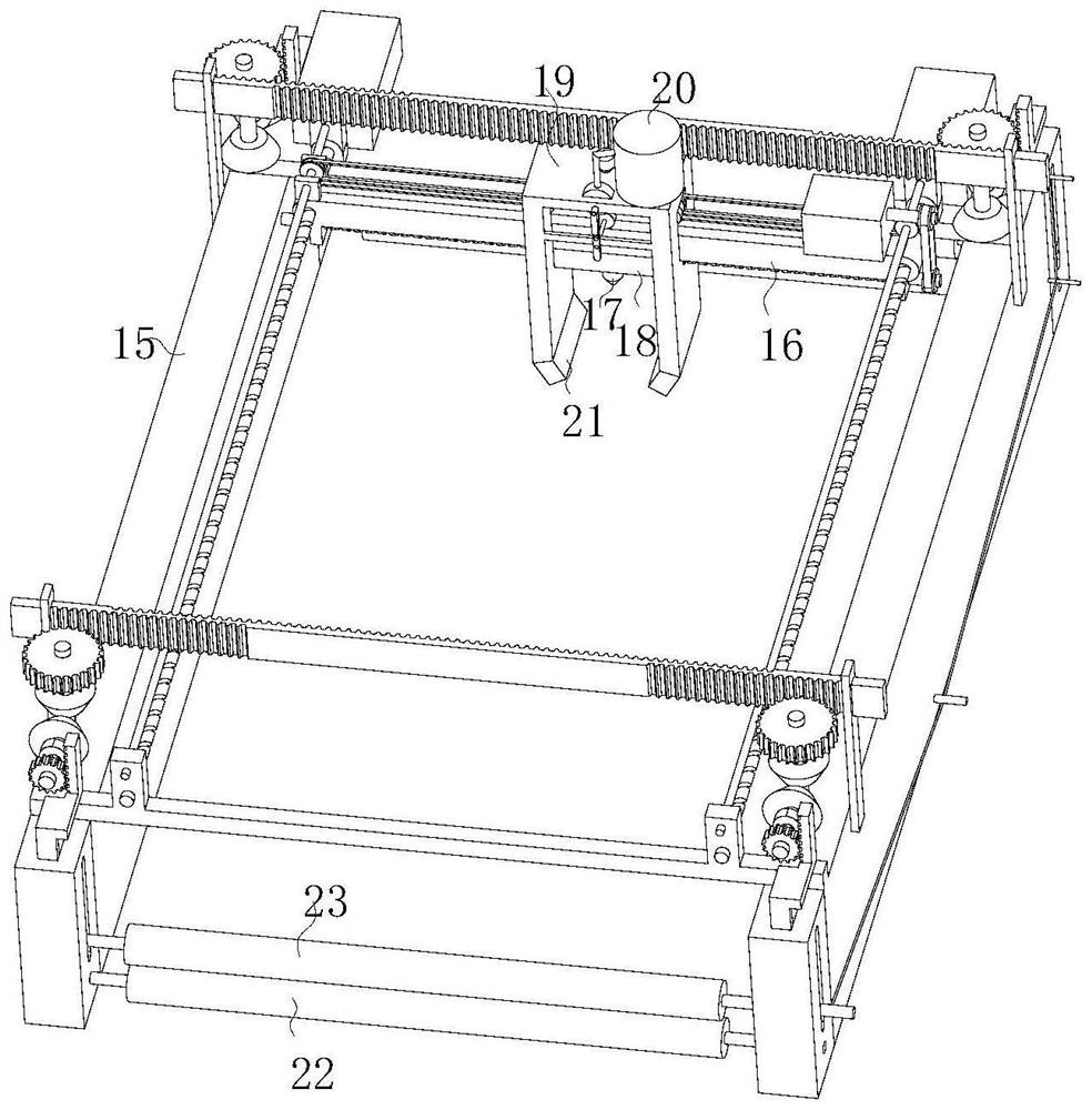
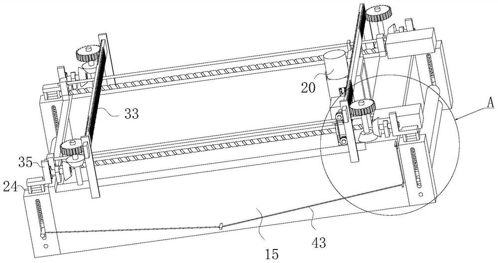
[0037] see Figure 1-13 , a laser parallel processing equipment, including a transmission positioning mechanism, a dust removal mechanism and a machining center mechanism arranged on the worktable 11;

[0038] The transmission positioning mechanism includes a feeding port 12 and a discharging port 13 respectively arranged at both ends of the worktable 11, and a positioning table 14 arranged between the feeding port 12 and the dischargi...


PUM


Abstract

The invention discloses laser parallel machining equipment in the field of laser machining. The laser parallel machining equipment comprises a transmission positioning mechanism, a dust removal mechanism and a machining center mechanism which are arranged on a workbench. The machining center comprises a complete machine bridge frame, a supporting plate and ball screw feeding units in the X direction and the Y direction, a laser transmitter connected with the ball screw feeding units is arranged on the supporting plate, and the laser transmitter is installed on the supporting plate in the Y direction in a sliding mode through a sliding base. The dust removal device comprises a dust suction unit fixedly arranged on a mounting base, and the mounting base is vertically mounted on the supporting plate in a sliding mode. The dust removal mechanism is arranged beside the laser transmitter, so that the dust removal mechanism can synchronously move along with the laser transmitter; in addition, the dust removal mechanism is arranged to be in a lifting type, the height of the dust removal mechanism can be freely adjusted, the height of the dust removal mechanism can be freely adjusted when the dust removal mechanism faces workpiece substrates with different thicknesses, the dissipation distance of dust on the workbench is reduced, and the dust removal efficiency is improved.

Description

technical field [0001] The invention belongs to the field of laser processing, and specifically relates to a laser parallel processing equipment. Background technique [0002] Laser processing is a non-contact processing method, which has the advantages of high energy, good directionality, high coherence, and small heat-affected zone, and is favored in the field of industrial processing. Traditional laser processing mainly uses a single beam of laser focusing to process materials. Since the beam energy emitted by the laser is too large, it is often necessary to use attenuation devices to attenuate the laser power, so the energy utilization rate during processing is not high. The existing laser processing equipment is mainly processed by scanning. This method can avoid contact with the material during processing and effectively reduce the impact of the processing process on the workpiece substrate. However, the processing efficiency is low and the utilization rate of laser en...

Claims


Application Information

Patent Timeline
Patent Type & Authority Applications(China)
IPC IPC(8): B23K26/16B23K26/70
CPCB23K26/16B23K26/702
Inventor 赵全忠付强梅志朋冯英国丁建一孔兵徐冰
Owner NANJING TRIZ INST OF LASER APPL TECH CO LTD
Learn More