Condensed and blocked pipeline dredging equipment

A pipe plugging and equipment technology, applied in the field of dredging equipment, can solve the problems of undesigned heating pipes, high risk, and inability to guarantee the effect

Pending Publication Date: 2022-07-29
SHANXI LUAN COAL BASED CLEAN ENERGY
View PDF0 Cites 0 Cited by
  • Summary
  • Abstract
  • Description
  • Claims
  • Application Information

AI Technical Summary

Problems solved by technology

This kind of clogging is different from sewer clogging in daily life. The medium with high freezing point may exist in a solid state for several meters or even tens of meters inside the pipeline. Using high-pressure gas to rely on absolute pressure to push the clogging medium to move and clear it is extremely dangerous and the effect cannot be guaranteed. However, the use of conventional extended spring rotary dredges ca

Method used


Image

  • Condensed and blocked pipeline dredging equipment
  • Condensed and blocked pipeline dredging equipment
  • Condensed and blocked pipeline dredging equipment

Examples


Embodiment 1

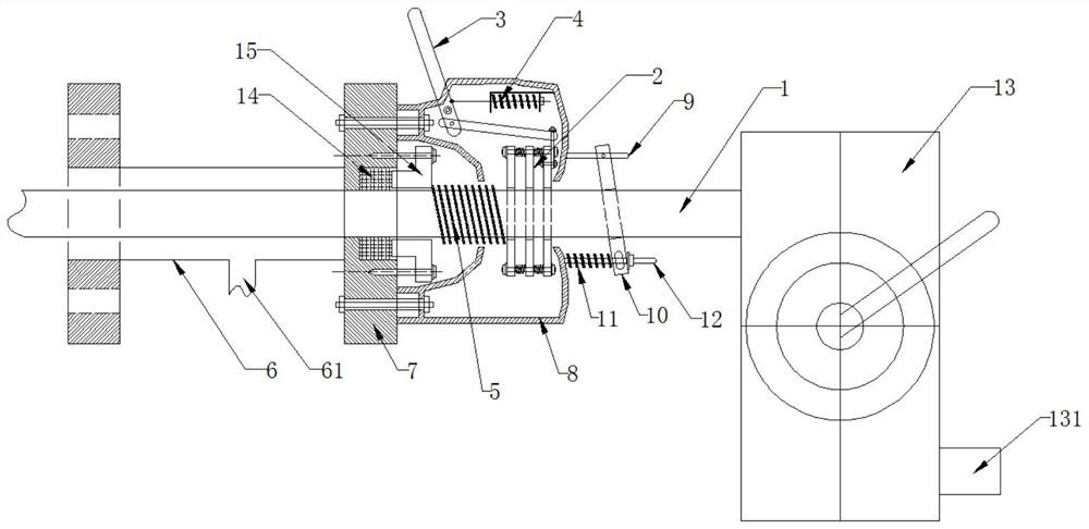
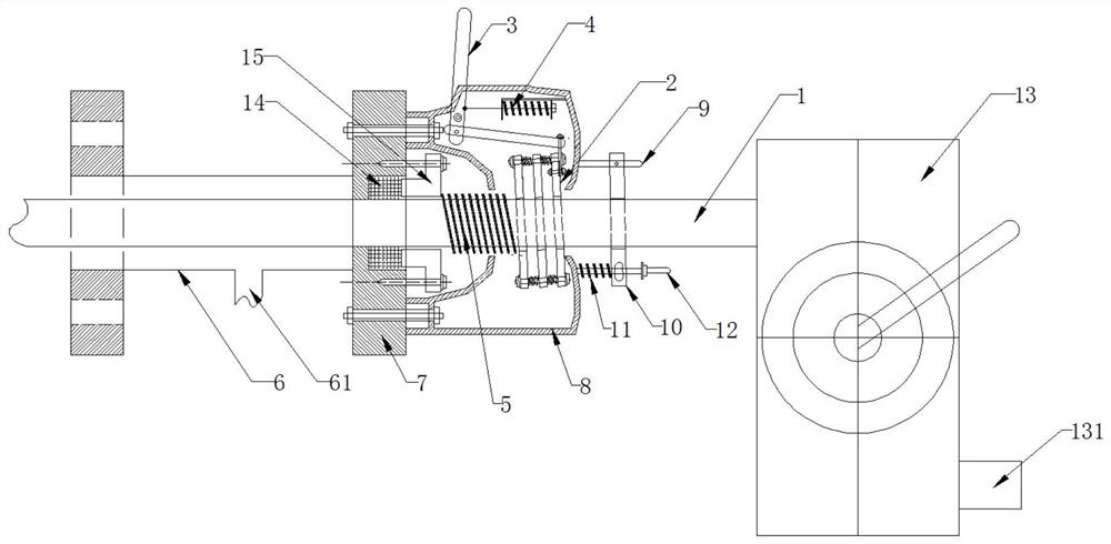
[0033] This embodiment provides a device for clearing a condensed and blocked pipeline, including a steam pipeline 1, a propulsion mechanism and a non-return mechanism. One end is used for introducing steam, the propulsion mechanism drives the steam pipeline 1 to move to the condensing pipeline synchronously or separates from the steam pipeline 1 and moves in the opposite direction to reset, and the non-return mechanism is used for the propulsion mechanism. The steam pipe is secured during reverse movement.

[0034] Wherein, the steam pipeline 1 can be a high-pressure and high-temperature-resistant rubber hose lined with steel mesh, or a high-pressure and high-temperature-resistant pipeline made of other materials. The steam pipeline 1 is preferably made of a material that can be bent, so that it can enter into the curved condensate pipeline. The diameter of the steam pipeline 1 needs to consider the diameter of the condensing pipeline, so as to ensure that the steam pipeline...

Embodiment 2

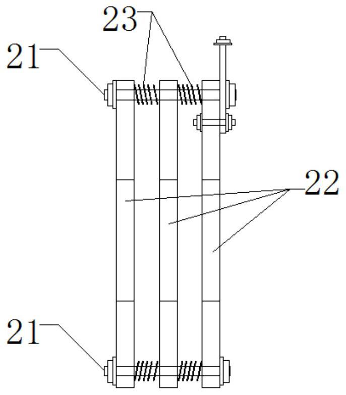
[0038] On the basis of Embodiment 1, for the propulsion mechanism, a manipulator can be used to grasp the steam pipeline 1 and move to the condensing pipeline, the manipulator can move in the opposite direction after releasing the steam pipeline 1, and the above-mentioned manipulator can automatically grasp or reset according to the control instruction. The loosening can be realized by using the prior art, and details are not repeated here; or the propulsion mechanism can also be: the propulsion mechanism includes a propulsion plate assembly 2, a propulsion handle 3 and a first elastic member 4, and the steam pipe 1 Pass through the pusher plate assembly 2 and move synchronously under the drive of the pusher plate assembly 2 when it moves to the blockage pipeline, and when the pusher plate assembly 2 moves in the opposite direction and resets with the pusher plate assembly 2 separation, one end of the push handle 3 is connected to the push plate assembly 2 and can drive the pus...

Embodiment 3

[0043] On the basis of Embodiment 2, the propulsion mechanism further includes a second elastic member 5, and the second elastic member 5 exerts a force on the propulsion plate assembly 2 to keep it away from the clogged pipeline.

[0044] After the pushing handle 3 is released, the second elastic member 5 assists the restoration of the pushing plate assembly 2 .

[0045] Wherein, the second elastic member 5 may be a coil spring, a butterfly spring or other elastic parts.


PUM


Abstract

The invention relates to a congealed and blocked pipeline dredging device which comprises a steam pipeline, a pushing mechanism and a non-return mechanism, one end of the steam pipeline is used for stretching into the congealed and blocked pipeline, the other end of the steam pipeline is used for introducing steam, and the pushing mechanism drives the steam pipeline to synchronously move towards the congealed and blocked pipeline or to be separated from the steam pipeline and reversely move and reset. And the non-return mechanism is used for fixing the steam pipeline when the propelling mechanism moves reversely. The method has the beneficial effects that on the basis of the characteristic of high condensation point of the condensation and blockage medium, common steam of a chemical device is used as a medium to melt and carry exhausted gas. The propelling mechanism drives the steam pipeline to move to a condensation and blockage point in the condensation and blockage pipeline, the steam pipeline enables steam to directly reach the condensation and blockage point, high temperature and high pressure of the steam serve as a heat source for melting a condensation and blockage medium, and the steam further has a gas carrying effect for conveying the condensation and blockage medium. A non-return mechanism is arranged on the steam pipeline, so that the steam pipeline is prevented from retreating along with the propelling mechanism or retreating due to steam blowback force.

Description

technical field [0001] The invention relates to a dredging device, in particular to a dredging device for a clogged pipeline. Background technique [0002] Some chemical process production involves high freezing point medium, and related common pipelines are designed with heat tracing to ensure that the temperature of the pipeline is higher than the freezing point of the medium. Blockage will occur. This kind of blockage is different from sewer blockage in life. The medium with high freezing point may exist in a solid state for several meters or even tens of meters inside the pipeline. Using high-pressure gas to rely on absolute pressure to push the blocking medium to move and dredge is extremely dangerous and cannot guarantee the effect. However, using the conventional extended spring rotary dredging machine cannot break the clogged medium and discharge it. After a heat tracing pipeline needs to be melted for a long time after troubleshooting, pressure dredging can be use...

Claims


Application Information

Patent Timeline
IPC IPC(8): B08B9/032B08B9/027
CPCB08B9/032B08B9/027B08B2209/032B08B2209/027
Inventor 连雅李陆山雷昌兴苗立壮杨龙呼延俊敬
Owner SHANXI LUAN COAL BASED CLEAN ENERGY
Why Eureka
Try Eureka