Gynecological operating bed with disinfection function
A gynecological surgery and functional technology, applied in the field of operating beds, can solve the problems of sterilization and disinfection, unable to wipe the bed, etc.
- Summary
- Abstract
- Description
- Claims
- Application Information
AI Technical Summary
Problems solved by technology
Method used
Image
Examples
Embodiment 1
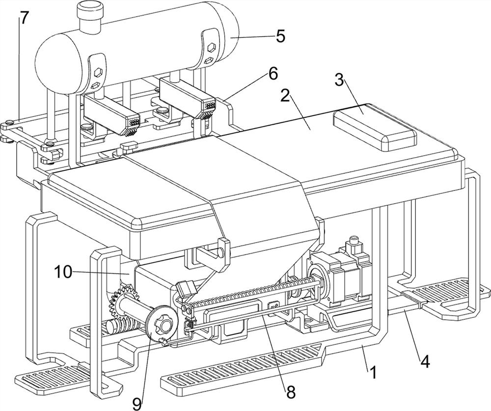
[0034] A gynecological operating bed with disinfection function, such as Figure 1-4 As shown, it includes a bed frame 1, a mattress 2, a pillow 3, a wiping mechanism 4 and a disinfection mechanism 5, the bed frame 1 is evenly spaced with four, and the mattress 2 is bolted between the upper sides of the four bed frames 1, A pillow 3 is placed on the right side of the top of the mattress 2 , a wiping mechanism 4 is provided on the bed frame 1 , and a disinfection mechanism 5 is provided on the mattress 2 .
[0035] like image 3As shown, the wiping mechanism 4 includes a mounting plate 41, a high temperature box 42, a sterile cloth 43, a first support shaft 44, a second support shaft 45, a servo motor 46, a motor support plate 47 and a first rotating shaft 48. The mattress 2 A first support shaft 44 is rotatably penetrated on both the front and rear sides, and a mounting plate 41 is bolted between the bed frames 1 on the left and right sides. There is a second support shaft 4...
Embodiment 2
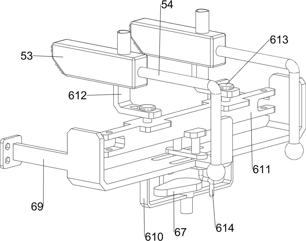
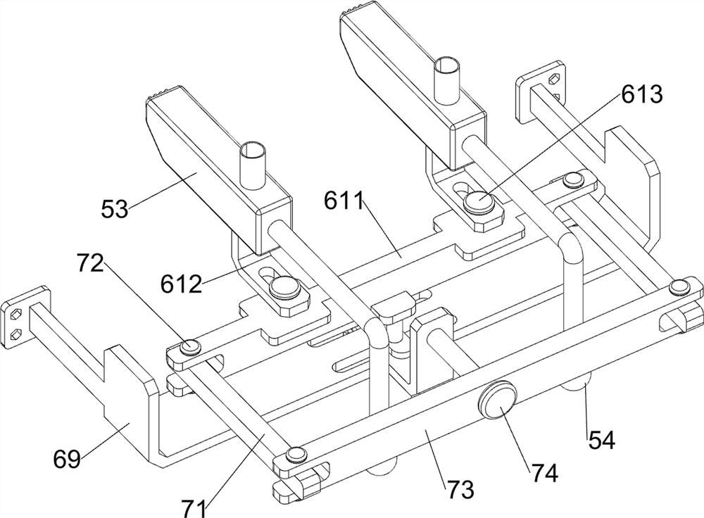
[0039] On the basis of Example 1, as figure 1 , Figure 5 and Image 6 As shown, a rotating mechanism 6 is also included. The rotating mechanism 6 includes a first pulley 61, a flat belt 62, a second pulley 63, a second rotating shaft 64, a first bevel gear 65, a second bevel gear 66, a cam 67, a first The second support plate 68, the third support plate 69, the first bracket 610, the sliding block 611, the connecting block 612, the first connecting shaft 613 and the elastic rod 614, the rear side of the mattress 2 is connected with the third support plate 69, the third support A second support plate 68 is bolted on the right side of the bottom of the plate 69 , and a second shaft 64 is rotatably penetrated through the lower part of the second support plate 68 . Pulley 61, a flat belt 62 is arranged between the second pulley 63 and the first pulley 61, a first bracket 610 is bolted on the middle side of the bottom of the third support plate 69, and a shaft is rotated through...
Embodiment 3
[0043] On the basis of Example 2, as figure 1 , Figure 8 and Figure 9 As shown, it also includes a cutting mechanism 8 for cutting the sterile cloth 43, and the cutting mechanism 8 includes a second bracket 81, a second guide rod 82, a first spring 83, a blade 84, a third guide rod 85, a second The spring 86 and the first wedge-shaped block 87, the front side of the high temperature box 42 is bolted with a second bracket 81, and the right part of the second bracket 81 is welded with two second guide rods 82 arranged in front and rear symmetry, and two second guide rods A blade 84 that can be in contact with the sterile cloth 43 is slidably sleeved between 82 , and a first spring 83 for power output is connected between the blade 84 and the second bracket 81 and is arranged around the outside of the rear second guide rod 82 for power output. , the left part of the second bracket 81 is slidably provided with two third guide rods 85 arranged symmetrically in the front and rea...
PUM
 Abstract
Description
Claims
Application Information
 - R&D
- Intellectual Property
- Life Sciences
- Materials
- Tech Scout
- Unparalleled Data Quality
- Higher Quality Content
- 60% Fewer Hallucinations
Browse by: Latest US Patents, China's latest patents, Technical Efficacy Thesaurus, Application Domain, Technology Topic, Popular Technical Reports.
© 2025 PatSnap. All rights reserved.Legal|Privacy policy|Modern Slavery Act Transparency Statement|Sitemap|About US| Contact US: help@patsnap.com


