Nuclear power plant pump equipment

A technology of power plants and nuclear energy, applied in the field of pump equipment, can solve problems such as laborious work and radiation exposure of operators, and achieve the effects of reducing radiation exposure, reducing radiation exposure, and reducing costs

Inactive Publication Date: 2004-04-28
KK TOSHIBA
View PDF0 Cites 0 Cited by
  • Summary
  • Abstract
  • Description
  • Claims
  • Application Information

AI Technical Summary

Problems solved by technology

Therefore, it is very laborious during operation, especially for pumps that transport radioactive fluids, and there is also the problem that workers are exposed to radiation.

Method used


Image

  • Nuclear power plant pump equipment
  • Nuclear power plant pump equipment
  • Nuclear power plant pump equipment

Examples


Embodiment Construction

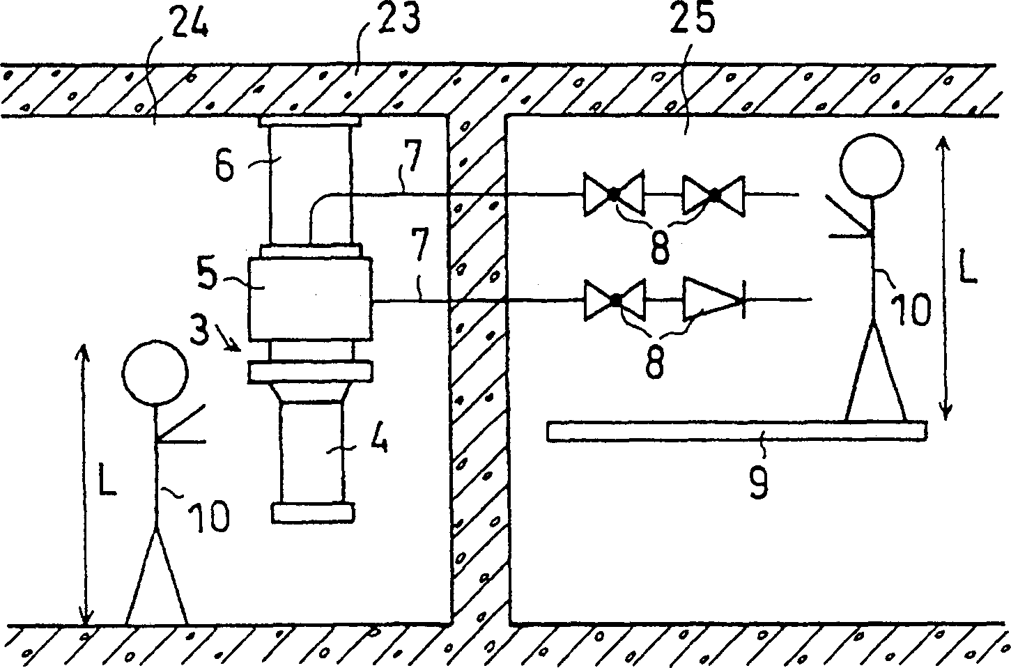
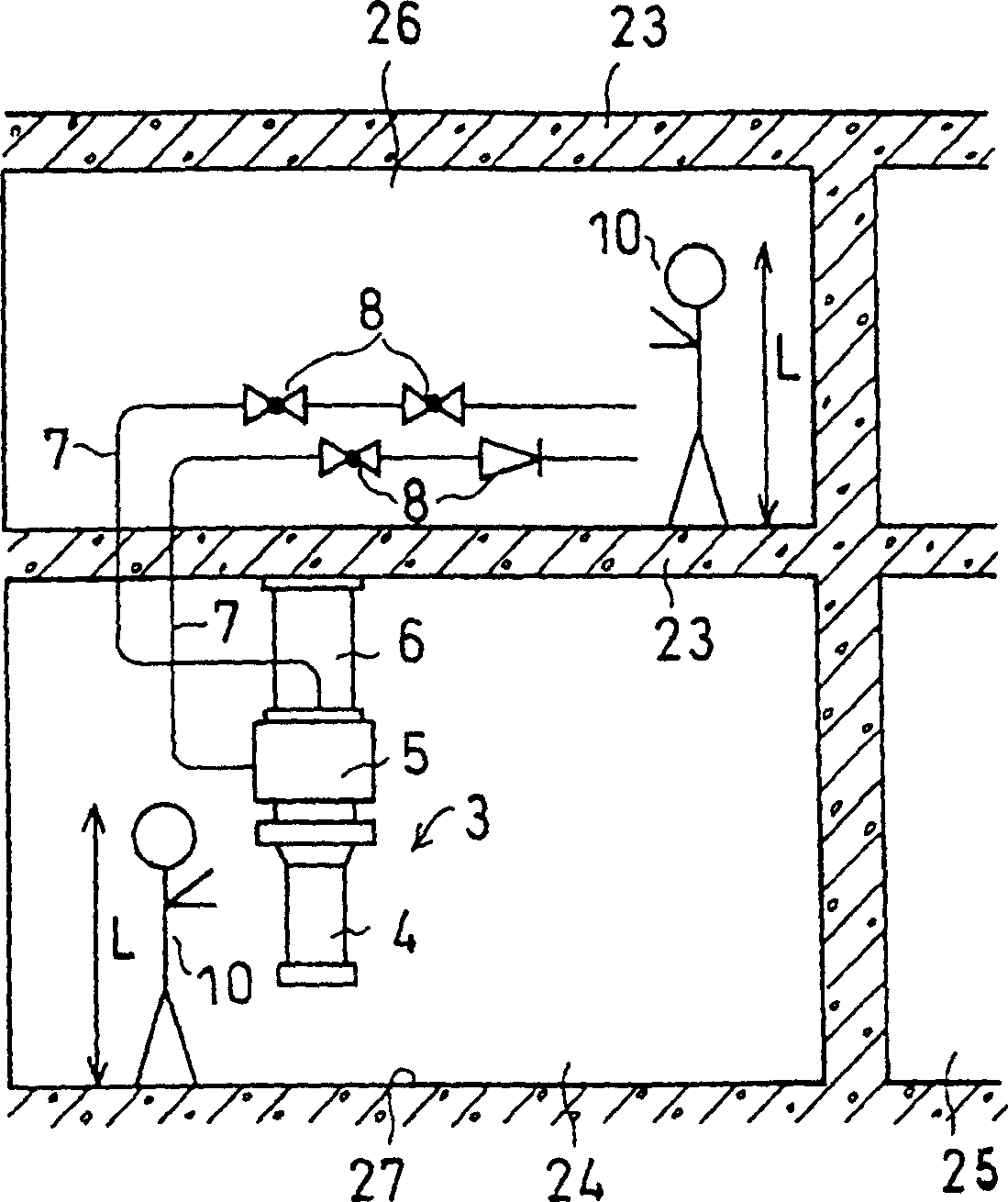
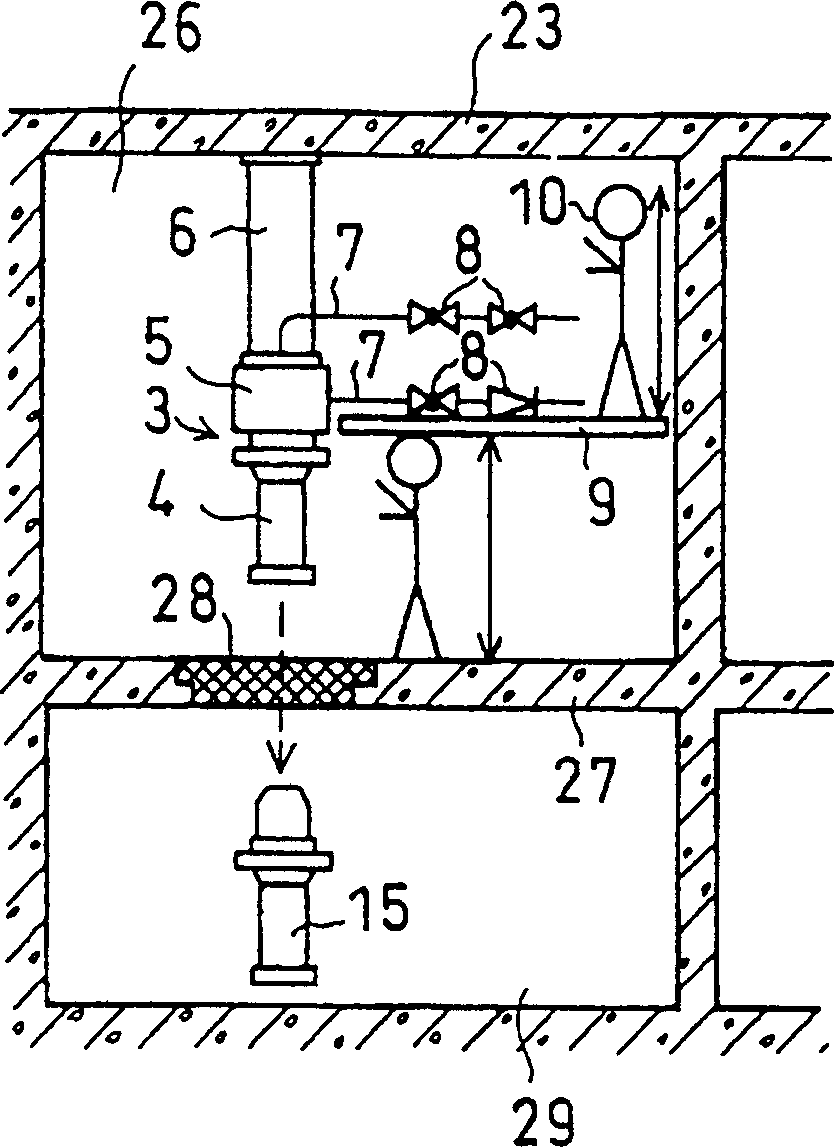
[0049] Refer below figure 1 A first embodiment of the vertical shaft pump equipment of the present invention will be described.

[0050] exist figure 1 neutralize Figure 16 The same parts are given the same reference numerals. Repeated parts are omitted. In this embodiment, a machine room 24 with a floor height lower than that of the conventional example is provided in the building body 23. In this machine room 24, the vertical shaft pump 3 is suspended from the ceiling. A pipe 7 and a suction valve and a discharge valve (hereinafter referred to as a valve) 8 are arranged in the provided adjacent chamber 25 .

[0051] That is, in figure 1 Among them, the piping 7 and the valve 8 attached to the vertical shaft pump 3 are arranged in the adjacent chamber 25 adjacent to the machine room 24 where the vertical shaft pump 3 is installed, and the vertical shaft pump 3 and the valve 8 are arranged in parallel. In the pump area like this, because there is no valve, just needn'...


PUM


Abstract

The invention can reduce the exposure of workers during checkup by efficiently arranging a vertical axis pump with hanging type support, suction valve and discharge valve of the pump and the shortest piping including radioactive fluid without increasing the component arrangement area, the dimensions and volume of building. A vertical pump and suction valves and discharge valves accompanying the vertical pump supported from the building ceiling or wall are arranged in a neighboring building to the pump station or upstairs or downstairs thereof so that the pump body and valves are separated in placing positions. By separating in this manner, checking capability for the vertical pump and valves is ensured, economical piping route is constituted and the building height can be limited to the pump height plus pump maintenance height in the pump arrangement area. Also, the building height in the valve area can be only maintenance height, so the building inside height can be reduced and exposure during disassembling and checkup work can be reduced by separating the maintenance work area.

Description

technical field [0001] The invention relates to a pump device for a nuclear power plant. Background technique [0002] Refer below Figure 16 Description of pumping equipment in existing nuclear power plants. exist Figure 16 Among them, the reference numeral 1 is, for example, the building body of a nuclear power plant, 2 is a machine room, and 3 is a vertical shaft pump. The vertical shaft pump 3 is mainly composed of a pump body 4 and a pump casing 5 , and is suspended from the ceiling of the machine room 2 via a pump bracket 6 . [0003] In a nuclear power plant, in order to ensure that the maintenance performance of the pump main body 4 and the maintenance performance of the suction valve and discharge valve 8 attached to the piping 7 of the vertical shaft pump 3 are not particularly affected by the piping route, the pump is suspended from the building body 1, etc. The installed vertical shaft pump 3 is installed in the machine room 2 with a high floor level. [0004...

Claims


Application Information

Patent Timeline
Patent Type & Authority Patents(China)
IPC IPC(8): G21C13/00G21D1/04
CPCY02E30/40Y02E30/00Y02E30/30
Inventor 平井秀男横山茂树
Owner KK TOSHIBA
Why Eureka
Try Eureka